


6
ASSEMBLY / PRE-OPERATION
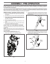
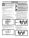
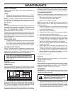
CHECK TIRE PRESSURE
The tires on your snow thrower were overinflated at the fac-
tory for shipping purposes. Correct and equal tire pres sure
is important for best snow throwing performance.
• Reduce tire pressure to 14-17 PSI.
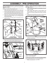
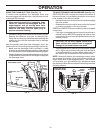
CONTROL LEVER
KNOB KNOB
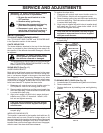
INSTALL CHUTE DEFLECTOR REMOTE CONTROL
(See Figs. 6 and 7)
1. Install remote cable bracket to discharge chute with
5/16-18 carriage bolt and 5/16-18 locknut as shown.
Tighten securely.
2. Install remote cable eyelet to chute deflector with
1/4-20 shoulder bolt and 1/4-20 locknut as shown.
Tighten nut securely. Eyelet will be loose on shoulder
bolt.
3. Install spring hooks between hex nuts on chute rotator
head and into hole in chute deflector as shown.
FIG. 6
HOOK
BE TWEEN
HEX NUTS
ON CHUTE
ROTATOR
HEAD
SPRING
CHUTE
DE FLEC TOR
5/16-18
CARRIAGE
BOLT
5/16-18
LOCKNUT
REMOTE
CABLE
BRACKET
1/4-20
LOCK NUT
CABLE
EYELET
1/4-20
SHOULDER
BOLT
FIG. 7
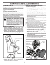
INSTALL DISCHARGE CHUTE / CHUTE ROTATOR HEAD
(See Fig. 4 and 5)
NOTE: The multi-wrench provided in your parts bag may
be used to install the chute rotator head.
1. Place discharge chute assembly on top of chute base
with discharge opening toward front of snow thrower.
2. Position chute rotator head over chute bracket. If nec es-
sary, rotate chute assembly to align square and pin on un-
der side of chute rotator head with holes in chute brack et.
3. With chute rotator head and chute bracket aligned,
po si tion chute rotator head on pin and threaded stud
of mounting bracket.
4. Install locknut and cable guide on threaded stud and
tighten securely.
FIG. 4
CHUTE
ROTATOR
HEAD
CABLE GUIDE
LOCKNUT
THREADED
STUD
PIN
ROTATOR HEAD
MOUNT ING
BRACKET
CHUTE
BRACKET
ALIGN BEFORE
TIGHTENING LOCKNUT
4. Install all 3 control lever knobs by pressing them down
onto the control levers.
FIG. 5
CABLE GUIDE
ROTATOR
CABLES
ROTATOR
CABLES
DOUBLE
CLIP
5. Place rotator cables through cable guide and secure
cables to the lower handle using the double clip.