


7
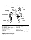
FIG. 2
ASSEMBLY
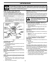
FIG. 3A
NOTE: You may now roll or drive your tractor off the skid.
Follow the ap pro pri ate instruction below to remove the
tractor from the skid
.
TO ROLL TRACTOR OFF SKID (See Op-
er a tion section for location and function of
con trols)
• Press lift lever plunger and raise attachment lift lever
to its highest po si tion.
• Release parking brake by de press ing clutch/brake
ped al.
• Place freewheel control in "trans mis sion dis en gaged
position" (See “TO TRANS PORT” in the Op er a tion
section of this manual).
• Roll tractor forward off skid.
• Remove banding holding the defl ector shield up against
tractor.
TO DRIVE TRAC TOR OFF SKID (See Op-
er a tion section for location and function of
con trols)
WARNING: Before start ing, read, un der stand and fol low
all in struc tions in the Op er a tion section of this man u al. Be
sure tractor is in a well-ventilated area. Be sure the area in
front of tractor is clear of other peo ple and objects.
• Be sure all the above assembly steps have been com-
pleted.
• Check engine oil level and fi ll fuel tank with gasoline.
• Place freewheel control in "trans mis sion en gaged"
po si tion (see "TO TRANSPORT" in Op er a tion section
of this manual).
• Sit on seat in operating position, depress clutch/brake
pedal and set the parking brake.
• Place motion control lever in neutral (N) position.
• Press lift lever plunger and raise attachment lift lever
to its highest position.
• Start the engine. After engine has started, move throttle
control to idle position.
• Release parking brake.
• Slowly move the mo tion control lever for ward and slowly
drive tractor off skid.
• Apply brake to stop trac tor, set park ing brake and place
motion con trol lever in neutral po si tion.
• Turn ignition key to "STOP" position.
Continue with the in struc tions that follow.
02466
02464
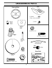
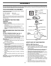
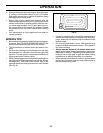
SEAT PAN
SHOULDER
BOLT
ADJUSTMENT
KNOB
FLAT WASHER
SEAT
02602
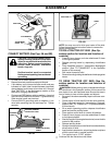
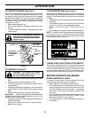
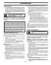
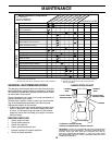
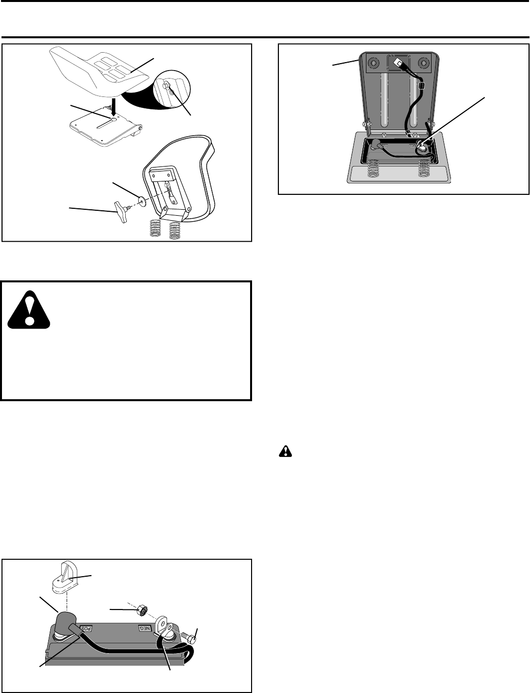
CONNECT BATTERY (See Figs. 3A and 3B)
CAUTION: Do not short battery termi-
nals by allowing a wrench or any other
object to contact both terminals at the
same time. Before connecting battery,
remove metal bracelets, wristwatch
bands, rings, etc.
Positive terminal must be connected
fi rst to prevent sparking from accidental
ground ing.
• Lift seat pan to raised position.
• Remove terminal protective caps and discard.
• If this battery is put into service after month and year
indicated on label (label located between terminals)
charge battery for minimum of one hour at 6-10 amps.
(See "BATTERY" in the Maintenance section of this
manual for charg ing in struc tions).
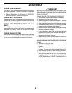
• First connect RED battery cable to positive (+) terminal
with hex bolt and keps nut as shown. Tighten securely.
Slide terminal cover over terminal.
• Connect BLACK grounding cable to negative (-) ter-
minal with remaining hex bolt and keps nut. Tighten
securely.
02604
HEX BOLT
NEGATIVE (BLACK)
CABLE
POSITIVE (RED)
CABLE
KEPS
NUT
SEAT PAN
TERMINAL
COVER
DISCARD TER MI NAL
PROTECTIVE CAPS
LABEL
FIG. 3B