24
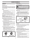
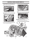
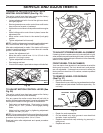
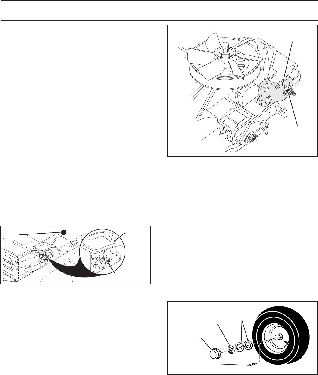
TO REMOVE WHEEL FOR REPAIRS
(See Fig. 37)
• Block up axle securely.
• Remove axle cover, retaining ring and washers to allow
wheel removal (rear wheel contains a square key - Do
not lose).
Fig. 37
RE TAIN ING
RING
WASH ERS
SQUARE KEY (REAR
WHEEL ONLY)
AXLE
COVER
SERVICE AND ADJUSTMENTS
Fig. 35
Fig. 36
• Repair tire and reassemble.
• On rear wheels only: align grooves in rear wheel hub
and axle. Insert square key.
• Replace washers and snap retaining ring securely in
axle groove.
• Replace axle cover.
ADJUSTMENT
BOLT
NEUTRAL
LOCK
GATE
MOTION CONTROL
LEVER
TRANSAXLE MOTION CONTROL LEVER
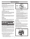
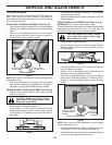
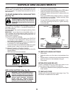
NEUTRAL ADJUSTMENT (See Fig. 35)
The motion control lever has been pre set at the factory
and adjustment should not be necessary.
• Loosen adjustment bolt in front of the right rear wheel,
and lightly tighten.
• Start engine and move motion control lever until tractor
does not move forward or backward.
• Hold motion control lever in that position and turn engine
off.
• While holding motion control lever in place, loosen the
adjustment bolt.
• Move motion control lever to the neutral (lock gate)
position.
• Tighten adjustment bolt securely.
NOTE: If additional clearance is needed to get to ad just ment
bolt, move mower deck height to the lowest position.
After above adjustment is made, if the tractor still creeps
forward or backward while motion control lever is in neutral
position, follow these steps:
• Loosen the adjustment bolt.
• Move the motion control lever 1/4 to 1/2 inch in the
direction it is trying to creep.
• Tighten adjustment bolt securely.
• Start engine and test.
• If tractor still creeps, repeat above steps until satisfied.
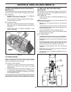
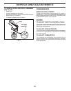
TO ADJUST MOTION CONTROL LE VER (See
Fig. 36)
The motion control lever has been pre set at the factory
and adjustment should not be necessary.
If for any reason the motion control lever will not hold its
position while at a selected speed, it may be adjusted at the
friction pack located on the right side of transmission.
• Park tractor on level surface. Stop tractor by turning
ignition key to “OFF” position, and engage parking
brake.
• Adjust motion control lever by tight en ing adjustment
locknut one half (1/2) turn.
NOTE: If for any reason the effort to move the motion control
lever be comes too excessive, reverse the above adjustment
procedure by loosening locknut 1/4 to 1/2 turn.
Road test tractor after adjustment and repeat procedure
if necessary.
01526
ADJUSTMENT
LOCKNUT
FRICTION
PACK
TO AD JUST STEER ING WHEEL ALIGN MENT
If steering wheel crossbars are not horizontal (left to right)
when wheels are positioned straight forward, remove steer -
ing wheel and reassemble per instructions in the Assembly
section of this manual.
FRONT WHEEL TOE-IN/CAMBER
Your new tractor front wheel toe-in and camber is set at the
factory and is normal. The front wheel toe-in and camber
are not adjustable. If damage has occurred to affect the
factory set front wheel toe-in or camber, contact a qualified
service center.


