


18
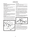
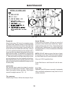
Motion Control Linkage Adjustment
This adjustment must be made with the rear
wheels rotating. Raise the rear of the machine
and block it up so the wheels are free to rotate.
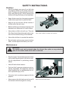
CAUTION: Keep hands, feet and clothing away
from rotating tires.
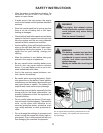
Tilt seat forward and remove the seat rod so the
seat may rotate forward onto the frame.
Place a 2x4 board between the foot plate and the
center of the seat to engage the seat safety switch.
Loosen the nuts directly behind each ball joint on
both rods that connect the pump arm to the mo-
tion control assemblies. FIG - 7
Start the engine. The park brake must be engaged
and the motion control levers in the neutral slots
to start the engine. Run the engine approximately
half throttle
Release park brake to allow the wheels to rotate.
SETUP AND ADJUSTMENTS
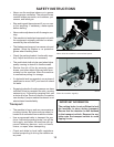
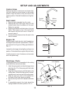
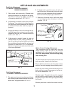
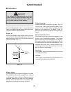
1. Stop engine and remove key. Release park
brake and measure the length of the spring.
The distance between the washer on each end
of the spring should be 2-7/8". FIG - 5
2. If adjustment is needed, loosen the nut below
the spring. Then rotate nut to desired position
so the proper distance between the washers
is obtained. Check other side for proper ad-
justment.
3. Engage the brake lever and measure the dis-
tance between the trunnion pin and the collar
welded to the brake rod. Distance should be
3/16" to 1/4". FIG - 5
4. If adjustment is needed, loosen the lock nut
directly below the yoke. Using a wrench, ro-
tate the rod by turning the double nuts using
the nuts below the yoke and the nut you just
loosened, to obtain the 3/16" to 1/4" distance.
Tighten nut against yoke and check other side
for proper adjustment.
FIG - 5
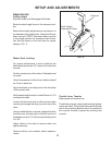
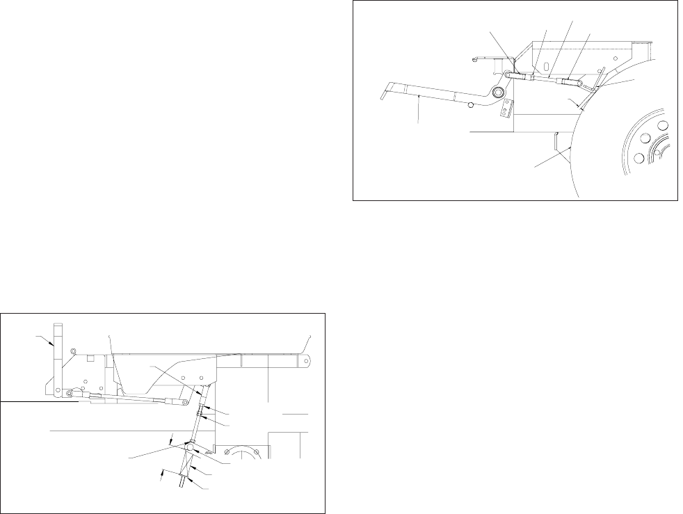
Park Brake Adjustment
For Models: 968999256, 968999257,
968999258, 968999259
Park Brake Adjustment
For Models: 968999254, 968999255
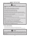
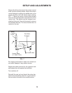
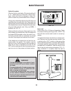
1. Stop engine and remove key, release park brake
and check the gap between the rear tire and the
brake arm. The gap should be 1/8” to 1/4”.
3. Make sure the brake arm on both sides does
not touch the tire when the brake is in the off
position. FIG - 6
2. If adjustment is needed, loosen the lock nut
next to the yoke. Remove the pin from the front
yoke so you can rotate the yoke on the adjust-
ment link until the proper gap is achieved.
FIG - 6
Park
Brake
Lever
Yoke
3/16 to 1/4
Gap Under Collar
2-7/8”
Lock Nut
Double Nuts
Trunnion Pin
Spring
Washer
Park Brake Lever
(in the off position)
Front Yoke
Lock Nut
Rear Tire
Adjustment Link
Yoke
Brake
Arm
1/8”-1/4”
Gap