5
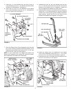
1. Move the lift lever backward to lower the sleeve hitch.
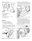
2. Attach an implement using the sleeve hitch pin. Tighten
the 5/8" x 2" stabilizer bolts against the im ple ment hitch
and then tighten the jam nuts. See fi gure 5 on page 4.
IMPORTANT:
Some im ple ments may require that the
sta bi liz er bolts not be tightened. Refer to your im ple ment
owner's manual.
3. The sleeve hitch is assembled in the lowest position by
the assembly instructions. If the implement attached to the
sleeve hitch is not level front to back during op er a tion:
a. Move the hex bolt in the lifting link to a hole (3 holes
available) that gives better levelling.
b. For closer adjustment, move the hex bolt assembled
in fi gure 1 to a position in the three position slot that
gives better levelling.
4. To tow an implement that has a tow hitch, simply re move
three clevis pins and then remove the Sleeve Hitch Lift
As sem bly from the Sleeve Hitch Frame Assembly.
5. To remove the entire Sleeve Hitch attachment, re move
the 5/8" x 1-3/4" hex bolt and 5/8" nylock nut which fasten
the bottom of the sleeve hitch to the tractor hitch, then
lift the attachment off the trac tor.
OPERATION
1. Clean off after each use.
2. Oil pivot points as needed.
3. Store in a dry location.
MAINTENANCE


