


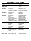

25
TO ADJUST STEERING WHEEL ALIGNMENT
If steering wheel crossbars are not horizontal (left to right)
when wheels are positioned straight forward, remove steer-
ing wheel and reassemble per instructions in the Assembly
section of this manual.
FRONT WHEEL TOE-IN/CAMBER
The front wheel toe-in and camber are not adjustable on
your tractor. If damage has occurred to affect the front
wheel toe-in or camber, contact your nearest authorized
service center/department.
SERVICE AND ADJUSTMENTS
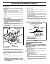
02239
ADJUSTMENT
BOLT
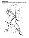
FIG. 32
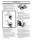
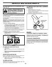
NEUTRAL
LOCK GATE
MOTION CONTROL
LEVER
TRANSAXLE MOTION CONTROL LE VER
NEUTRAL ADJUSTMENT(See Fig. 32)
The motion control lever has been pre set at the factory and
adjustment should not be necessary.
• Loosen adjustment bolt in front of the right rear wheel,
and lightly tighten.
• Start engine and move motion control lever until tractor
does not move forward or backward.
• Hold motion control lever in that position and turn engine
off.
• While holding motion control lever in place, loosen the
adjustment bolt.
• Move motion control lever to the neutral (N) (lock gate)
position.
• Tighten adjustment bolt securely.
NOTE: If additional clearance is needed to get to ad just ment
bolt, move mower deck height to the lowest position.
After above adjustment is made, if the tractor still creeps
forward or backward while motion control lever is in neutral
position, follow these steps:
TRANSMISSION REMOVAL/REPLACEMENT
Should your transmission require removal for service or
replacement, it should be purged after reinstallation and
before operating the tractor. See “PURGE TRANS MIS SION”
in the Operation section of this manual.
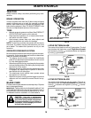
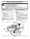
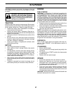
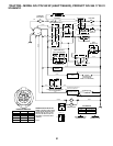
FIG. 31
02201
STATIONARY
IDLERS
TRANS MIS SION
IN PUT PULLEY
CLUTCHING
IDLER
ELECTRIC
CLUTCH
CLUTCH LOCATOR
CLUTCH
WIRE HAR NESS
BELT INSTALLATION -
• Carefully work new belt down around transmission
cooling fan and onto the input pulley.
• Pull belt toward front of tractor and roll belt around
electric clutch and onto engine pulley.
• Install belt through all stationary idlers and clutch ing
idler.
• Reinstall clutch locator and tighten nut securely.
• Reconnect clutch harness.
• Make sure belt is in all pulley grooves and in side all
belt guides and keep ers.
• Install mower (See “TO IN STALL MOWER” in this sec-
tion of manual).
• Loosen the adjustment bolt.
• Move the motion control lever 1/4 to 1/2 inch in the
direction it is trying to creep.
• Tighten adjustment bolt securely.
• Start engine and test.
• If tractor still creeps, repeat above steps until satis-
fi ed.
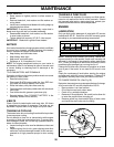
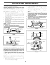
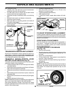
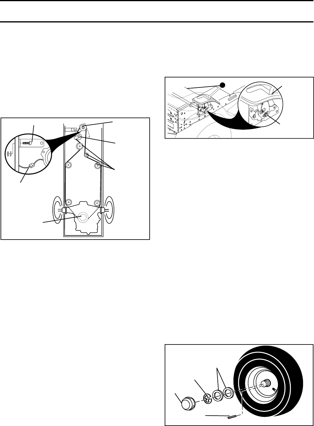
TO REMOVE WHEEL FOR REPAIRS
(See Fig. 33)
• Block up axle securely.
• Remove axle cover, retaining ring and washers to allow
wheel removal (rear wheel contains a square key - Do
not lose).
• Repair tire and reassemble.
• On rear wheels only: align grooves in rear wheel hub
and axle. Insert square key.
• Replace washers and snap retaining ring securely in
axle groove.
• Replace axle cover.
NOTE: To seal tire punctures and prevent fl at tires due to
slow leaks, tire sealant may be purchased from your local
parts dealer. Tire sealant also prevents tire dry rot and
corrosion.
FIG. 33
00
663
RE TAIN ING
RING
WASH ERS
SQUARE KEY
(REAR WHEEL ONLY)
AXLE COVER