


23
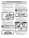
TO START ENGINE WITH A WEAK BATTERY
(SEE FIG. 40)
WARNING: Lead-acid batteries gen er ate
ex plo sive gases. Keep sparks, flame and
smoking ma te ri als away from bat ter ies.
Always wear eye pro tec tion when around
batteries.
If your battery is too weak to start the engine, it should be
recharged. (See "BATTERY" in the MAINTENANCE sec-
tion of this man u al).
If “jumper ca bles” are used for emer gen cy starting, follow
this pro ce dure:
IMPORTANT: YOUR TRACTOR IS EQUIPPED WITH A
12 VOLT SYSTEM. THE OTHER VEHICLE MUST ALSO
BE A 12 VOLT SYSTEM. DO NOT USE YOUR TRACTOR
BATTERY TO START OTHER VEHICLES.
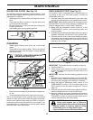
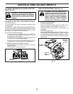
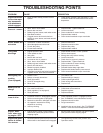
TO ATTACH JUMPER CABLES -
• Connect one end of the RED cable to the POSITIVE
(+) terminal of each battery(A-B), taking care not to
short against tractor chassis.
• Connect one end of the BLACK ca ble to the NEGA TIVE
(-) terminal (C) of fully charged battery.
• Connect the other end of the BLACK cable (D) to good
chassis ground, away from fuel tank and bat tery.
TO REMOVE CABLES, REVERSE ORDER -
• BLACK cable first from chassis and then from the fully
charged battery.
• RED cable last from both batteries.
WEAK OR DEAD
BATTERY
FULLY CHARGED
BATTERY
Fig. 40
SERVICE AND ADJUSTMENTS
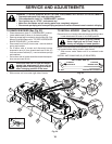
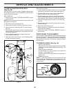
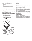
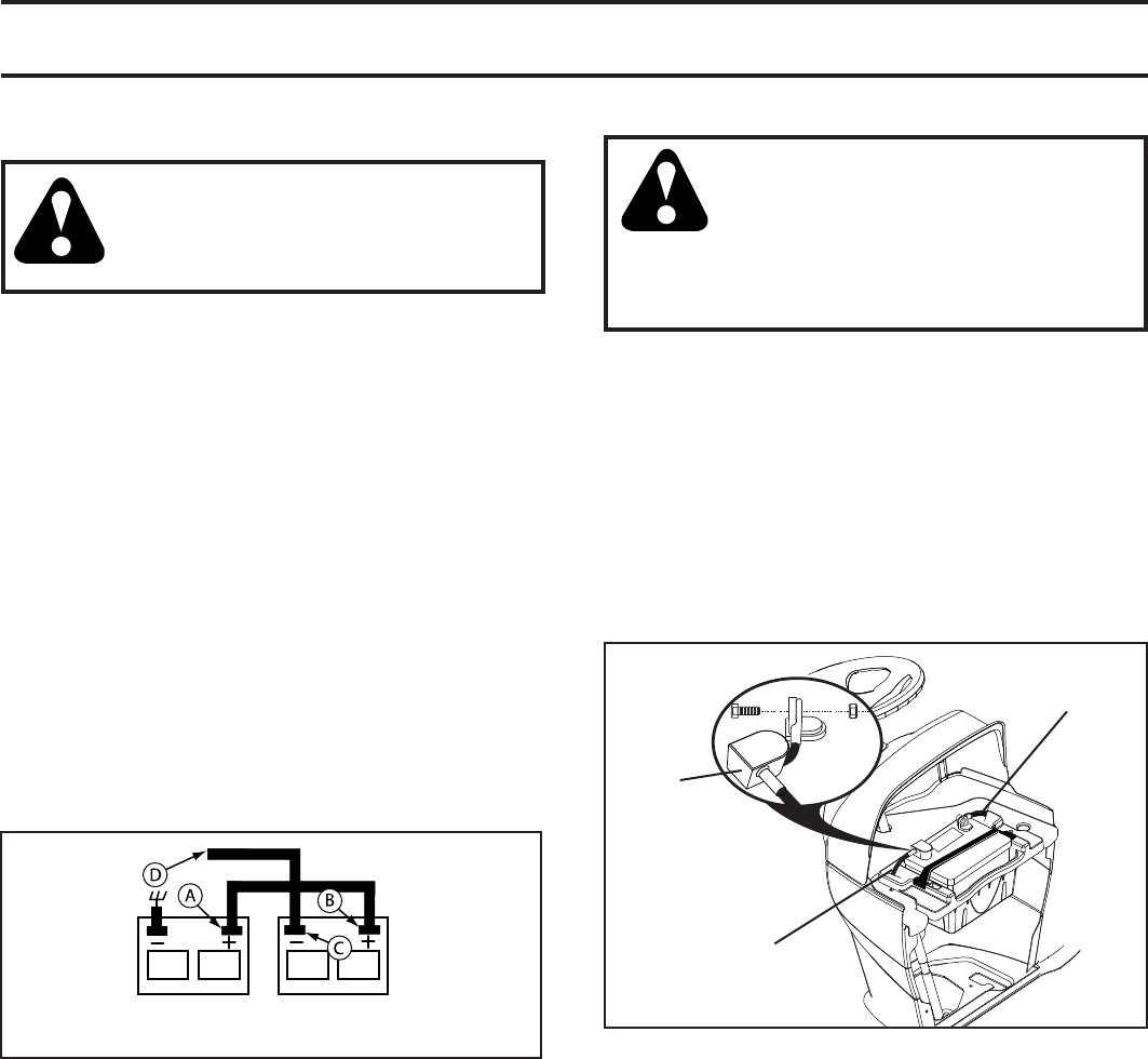
REPLACING BATTERY (See Fig. 41)
WARNING: Do not short battery ter mi-
nals by allowing a wrench or any other
object to contact both terminals at the
same time. Before connecting battery,
remove metal bracelets, wristwatch
bands, rings, etc. Positive terminal
must be connected first to prevent
sparking from ac ci den tal grounding.
• Lift hood to raised position.
• Remove terminal cover.
• Disconnect BLACK battery cable then RED battery
cable and carefully remove battery from tractor.
• Install new battery with terminals in same position as
old battery.
• Reinstall terminal cover.
• First connect RED battery cable to positive (+) battery
terminal with bolt and nut as shown. Tighten securely.
• Connect BLACK grounding cable to negative (-) bat tery
terminal with remaining bolt and nut. Tighten securely
• Close hood.
POSITIVE
(RED)
CABLE
TERMINAL
COVER
NEGATIVE
(BLACK)
CABLE
Fig. 41