


6
ASSEMBLY
FIG. 1
02931
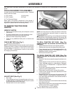
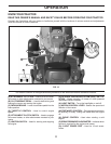
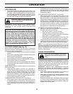
CHECK BATTERY (See Fig. 1)
• Lift hood to raised position.
NOTE: If this battery is put into service after month and year
indicated on label (L) (label is located between terminals)
charge battery for minimum of one hour at 6-10 amps.
(See "BATTERY" in Maintenance section of this manual
for charging instructions).
L
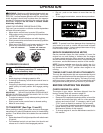
FIG. 2
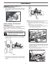
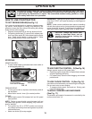
ADJUST SEAT (See Fig. 2)
• Sit in seat.
• Lift up adjustment lever (A) and slide seat until a com-
fortable position is reached which allows you to press
clutch/brake pedal all the way down.
• Release lever to lock seat in position.
NOTE: You may now roll or drive your tractor off the skid.
Follow the ap pro pri ate instruction below to remove the
tractor from the skid.
WARNING: Before start ing, read, un der stand and fol low
all in struc tions in the Op er a tion section of this man u al. Be
sure tractor is in a well-ventilated area. Be sure the area in
front of tractor is clear of other peo ple and objects.
TO ROLL TRACTOR OFF SKID (See Op-
er a tion section for location and function of
con trols)
• Raise attachment lift lever to its highest po si tion.
• Release parking brake by de press ing brake ped al.
• Place freewheel control in dis en gaged po si tion to dis-
en gage trans mis sion (See “TO TRANS PORT” in the
Op er a tion section of this manual).
• Roll tractor forward off skid.
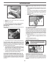
TO DRIVE TRAC TOR OFF SKID (See Op-
er a tion section for location and function of
con trols)
• Be sure all the above assembly steps have been com-
pleted.
• Check engine oil level and fi ll fuel tank with gasoline.
• Place freewheel control in "trans mis sion en gaged"
po si tion (see "TO TRANSPORT" in Op er a tion section
of this manual).
• Sit on seat in operating position, depress clutch/brake
pedal and set the parking brake.
• Place motion control lever in neutral (N) position.
• Press lift lever plunger and raise attachment lift lever
to its highest position.
• Remove key from bag and start the engine (see "TO
START ENGINE" in the Operation section of this man-
ual). After engine has started, move throttle control to
idle (slow) position.
• Release parking brake.
• Slowly move the mo tion control lever for ward and slowly
drive tractor off skid.
• Apply brake to stop trac tor, set park ing brake and place
motion con trol lever in neutral po si tion.
• Turn ignition key to "STOP" position.
Continue with the in struc tions that follow.
A
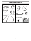
Your new tractor has been assembled at the factory with exception of those parts left unassembled for shipping pur-
poses.
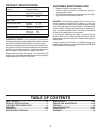
TOOLS REQUIRED FOR ASSEMBLY
A socket wrench set will make assembly easier. Stan dard
wrench sizes are listed.
(1) 3/4" wrench (1) Utility knife
(1) 9/16" wrench (1) Pliers
(1) Tire Pressure Gauge
When right or left hand is mentioned in this man ual, it
means from your point of view, when you are in the operat-
ing po si tion (seated be hind the steer ing wheel).
TO REMOVE TRACTOR FROM
CARTON
UNPACK CARTON
• Remove all accessible loose parts and parts cartons
from carton .
• Cut along dashed lines on all four panels of carton.
Remove end panels and lay side panels fl at.
• Remove mower and packing materials.
• Check for any additional loose parts or cartons and
remove.