27
S
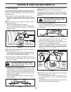
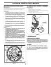
MARTSWITCH IGNITION SYSTEM LIGHTS
(See Fig. 49)
The SmartSwitch System is equipped with courtesy lights
that are used to indicate system functions or faults.
FUNCTIONS
• The SmartSwitch Ignition (SSI) Button (F) will blink blue
while waiting for the correct passcode to be entered.
The SSI button will blink green when tractor is ready
to start and remain solid green while running.
• The park brake symbol (CC) will be lit if the parking
brake has not been engaged during a start attempt.
• The blade switch symbol (EE) will blink if the attachment
clutch control is not in the "DISENGAGED" position
during a start attempt.
• The Reverse Operation System (ROS) button (G) will
be lit when Reverse Operation System is in use.
• The Headlight button (H) will remain lit while headlights
are in use.
• During normal operation, the Battery Indicator Button (I)
will not be lit.
FAULTS
• The SSI Button (F) will blink red for two seconds if the
wrong passcode has been entered.
• The Reverse Operation System (ROS) button (G) will
blink when there is a fault with the Reverse Opera-
tion System. See "Reverse Operation System" in the
Operation section of this manual.
• After the first unsuccessful start attempt, the Battery
Indicator Button (I) will blink for two (2) seconds and
then stay lit. This indicates that the battery voltage is
below normal operating level. While engine is in op-
eration, this light may also indicate a charging system
failure.
• The Headlight Button (H) will blink when one or both
of the headlight bulbs fail.
• All indicator lights will blink in the event the engine shuts
off for unknown reasons; for example, if the engine has
run out of fuel.
SERVICE AND ADJUSTMENTS
Fig. 49
TO REMOVE HOOD AND GRILL ASSEMBLY
(See Fig. 50)
• Raise hood.
• Unsnap headlight wire connector.
• Stand in front of tractor. Grasp hood at sides, tilt toward
engine and lift off of tractor.
• To replace, reverse above procedure.
ENGINE
TO AD JUST THROTTLE CON TROL CABLE
The throttle control has been preset at the factory and
ad just ment should not be necessary. If adjustment is nec-
es sary, see engine manual.
07002
HEADLIGHT
WIRE
CONNECTOR
HOOD
Fig. 50
TRANSMISSION
REMOVAL/RE PLACE MENT
Should your transmission require removal for service or
re place ment, it should be purged after reinstallation and
before operating the tractor. See “PURGE TRANS MIS SION”
in the Operation section of this manual.
F
I
H
G
CC
EE


