


8 – English
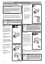
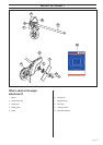
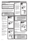
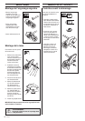
Assembling the blade
ASSEMBLY
Fit the blade as follows:
1. Fit the drive disc (A) on
the outgoing shaft. Make
sure that the edge that
fits in the hole of the
blade is facing outward.
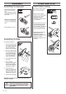
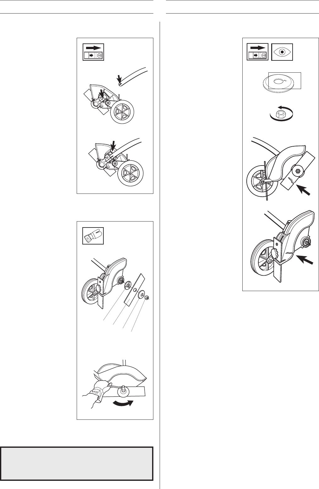
2. Block the blade rotation
by inserting locking pin
in the hole behind the
blade guard engaging it
in the corresponding
hole in the drive disc.
3. Fit the blade (B) on the
drive disc.
4. Fit the support
flange (C). The support
flange must be fitted
with its outer edge hard
up against the blade.
5. Fit the locknut (D).
NOTE! The locknut has
left-hand threads. The
tightening torque of the
locknut is 35 – 50 Nm.
6. Remove the locking pin.
A
C
B
D
NOTE! Do not forget to remove the locking pin before
using the machine.
!
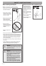
WARNING!
Under no circumstances may the edge
cutter blade be used without the blade
guard fitted.
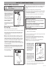
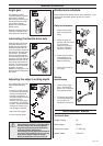
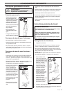
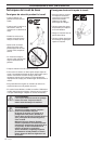
Assembling the angle gear
• Assemble the angle gear
back on the supporting
tube.
Turn the blade so that the
drive shaft engages in the
angle gear.
• Position the angle gear so
that its slot is aligned with
the line on the supporting
tube.
• Firmly tighten the screw.
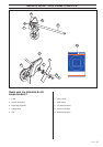
Control before starting
For reasons of safety follow
these recommendations!
• Check that the support
flange is not cracked due to
fatigue or due to being
tightened too much.
Discard the support flange
if it is cracked.
• Ensure that the nut has not
lost its tightening capacity.
The nut lock shall have a
locking torque of at least l.5
Nm. The nut’s tightening
torque shall be 35-50 Nm.
• Check that the blade and
blade guard are not
damaged or cracked.
Replace the blade or blade
guard if it has been
exposed to impact or if it is
cracked.
START AND STOP