


6
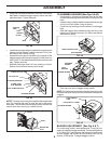
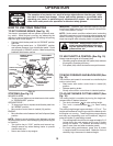
CONNECT BATTERY (See Figs. 2)
CAUTION: Do not short battery termi-
nals by allowing a wrench or any other
object to con tact both terminals at the
same time. Before connecting battery,
remove metal bracelets, wristwatch
bands, rings, etc.
Positive terminal must be connected
first to prevent sparking from accidental
ground ing.
• If this battery is put into service after month and year
indicated on label (label located between terminals)
charge battery for minimum of one hour at 6-10 amps.
(See "BATTERY" in the Maintenance section of this
manual for charg ing instructions).
• Remove battery cover.
• Remove terminal protective caps and discard.
• First connect RED battery cable to positive (+) ter-
minal with hex bolt and keps nut as shown. Tighten
securely.
• Connect BLACK grounding cable to negative (-) ter-
minal with remaining hex bolt and keps nut. Tighten
securely.
• Replace battery cover.
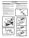
Open battery cover for:
• Inspection for secure connections (to tighten hard-
ware).
• Inspection for corrosion.
• Testing battery.
• Jumping (if required).
• Periodic charging .
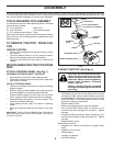
ASSEMBLY
TOOLS REQUIRED FOR ASSEMBLY
A socket wrench set will make assembly easier. Stan dard
wrench sizes are listed.
(2) 7/16" wrenches Utility knife
(1) 3/4" wrenches Tire pressure gauge
(1) 3/4" socket w/drive ratchet Pliers
When right or left hand is mentioned in this man ual, it means
when you are in the operating po si tion (seated be hind the
steer ing wheel).
TO REMOVE TRACTOR FROM CAR-
TON
UNPACK CARTON
• Remove all accessible loose parts and parts cartons
from carton.
• Cut along dashed lines on all four panels of carton.
Remove end panels and lay side panels flat.
• Check for any additional loose parts or cartons and
remove.
Your new tractor has been assembled at the factory with exception of those parts left unassembled for shipping purposes.
To ensure safe and proper operation of your tractor all parts and hardware you assemble must be tightened securely. Use
the correct tools as necessary to insure proper tightness.
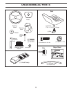
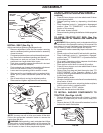
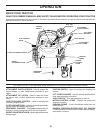
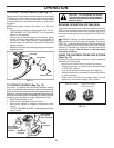
FIG. 1
03125
LOWER STEERING SHAFT
STEERING
BOOT
EXTENSION SHAFT
5/16 HEX BOLT
STEERING
WHEEL
INSERT
ADAPTER
LARGE FLAT WASHER
TABS
TAB
SLOTS
5/16 LOCK WASHER
BEFORE REMOVING TRACTOR FROM
SKID
ATTACH STEERING WHEEL (See Fig. 1)
ASSEMBLE EXTENSION SHAFT AND BOOT
• Slide extension shaft onto lower steering shaft.
• Place tabs of steering boot over tab slots in dash and
push down to secure.
INSTALL STEERING WHEEL
• Position front wheels of the tractor so they are pointing
straight forward.
• Remove steering wheel adapter from steering wheel
and slide adapter onto steer ing shaft ex ten sion.
• Position steering wheel so cross bars are hor i zon tal
(left to right) and slide inside boot and onto adapt er.
• Assemble large flat washer, 5/16 lock washer, 5/16
hex bolt and tighten se cure ly.
• Snap steering wheel insert into center of steer ing
wheel.
• Remove protective materials from trac tor hood and
grill.
IMPORTANT: CHECK FOR AND REMOVE ANY STAPLES IN
SKID THAT MAY PUNCTURE TIRES WHERE TRACTOR IS
TO ROLL OFF SKID.