


7
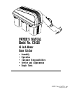
ASSEMBLY
REAR MOUNTING BRACKET and
SUPPORT TUBE
(See Figs. 1A, 1B & 1C)
Use Hardware - - GROUP "A"
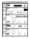
Before continuing with assembly, you must first determine
which type of drawbar your tractor is equipped with. Com-
pare your drawbar with the illustrations of "BEFORE YOU
START TO ASSEMBLE THE GRASS CATCHER" and
follow instructions given.
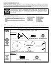
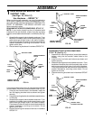
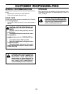
DRAWBAR WITH UPPER CORNER RIBS - STYLE "A"
NOTE: If your tractor already has four (4) shoulder bolts
installed on the rear drawbar, simply hang the mounting
bracket, lanced tabs towards bottom, on the bolts (See Fig.
1A).
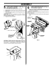
1. Assemble the support tube to drawbar as shown. From
backside of drawbar place reinforcement plate so that
weld screws go through holes in left side of drawbar.
Place support tube over weld screws and assemble flat
washer, lockwasher, and wing nut as shown Do not
tighten at this time.
2. Discard remaining hardware in hardware GROUP "A".
1
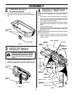
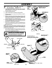
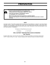
If your tractor does not have four (4) shoulder bolts installed
on the drawbar, follow the instructions below (See Fig. 1B).
1. Using the four formed holes in the drawbar, install the
four self tapping shoulder bolts as shown and tighten
securely.
2. Hang the mounting bracket, lanced tabs towards bottom,
on the bolts.
3. Assemble the support tube to drawbar as shown. From
backside of drawbar place reinforcement plate so that
weld screws go through holes in left side of drawbar.
Place support tube over weld screws and assemble flat
washer, lockwasher, and wing nut as shown Do not
tighten at this time.
4. Discard remaining hex bolts and locknuts in hardware
GROUP "A".
LANCED TABS
TOWARD BOTTOM
SHOULDER
BOLTS
FIG. 1A
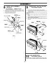
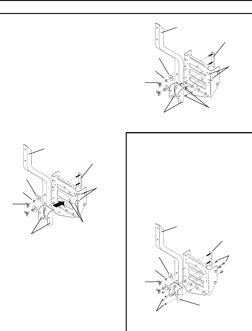
DRAWBAR WITHOUT UPPER CORNER RIBS -
STYLE "B" (See Fig. 1C)
1. Assemble the mounting bracket, lanced tabs towards
bottom, using the four smaller inside holes on the
drawbar.
2. Install the four hex bolts and locknuts as shown and
tighten securely.
3. Assemble the support tube to drawbar as shown. From
backside of drawbar place reinforcement plate so that
weld screws go through holes in left side of drawbar.
Place support tube over weld screws and assemble flat
washer, lockwasher, and wing nut as shown Do not
tighten at this time.
4. Discard remaining shoulder bolts in hardware GROUP
"A".
UPPER
CORNER
RIBS
REINFORCEMENT
PLATE
SUPPORT TUBE
FLAT
WASHERS
LOCK
WASHERS
WING
NUTS
LANCED TABS
TOWARD BOTTOM
SELF TAPPING
SHOULDER
BOLTS
FIG. 1B
UPPER
CORNER
RIBS
REINFORCEMENT
PLATE
SUPPORT TUBE
FLAT
WASHERS
LOCK
WASHERS
WING
NUTS
LANCED TABS
TOWARD BOTTOM
LOCKNUTS
FIG. 1C
HEX
BOLTS
REINFORCEMENT
PLATE
SUPPORT TUBE
FLAT
WASHERS
LOCK
WASHERS
WING
NUTS