


Hose clamps are not completely tight.
Please tighten hose clamps prior to using.
Hose clamps are left loose to extend life
of gaskets and ttings.
Oil cap gasket before using and
lubricate weekly so the gasket will seal
properly and prevent chemical leaks.
Oil check valve and keep breather
hole clear of debris. Your failure to oil
may cause the tank to collapse
and crack due to vacuum created by
pump lubricate with “3 and 1” oil.
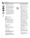
ASSEMBLY OF PUMP HANDLE PUMP
LEVER & PUMP MODULE
Pull sprayer, pump lever, pump handle,
spray wand, plastic bag (with washers
and pins), etc. out of box. Place parts in
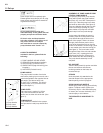
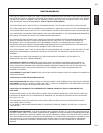
front of you. Take the pump lever, there
are bends on either side. (See gure 2).
Place one Washer through the bar, then
push lever through opening on pump,
place washer on pump lever and then
place hairpin lock and push through.
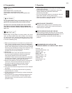
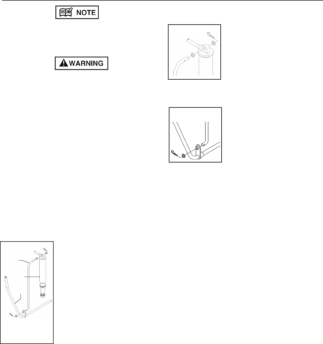
On the same side where the pump is
located, place the round portion of the
pump handle through the hole on the
base of the sprayer. When it is almost
through, place the bent portion of the
pump lever through the hole on the at
portion of the handle. Once through, place
on one washer and, then the locking pin.
(See gure 3). The round tube comes
through the base of the unit and extends
out 6.4mm (1/4”), exposing the hole
drilled through the tube. Place on the
other washer and the other holding pin.
The pump handle assembly is now
complete.
HIP SUPPORT
Take the black plastic hip portion and side
the two end sections into the two
receiving notches on the base, the
rounded side up.
STRAPS
Hook the plastic clip attached to the
shoulder straps into the appropriate
lateral opening on the hip support.
SPRAY WAND AND NOZZLE
Attach spray wand to spray gun and rmly
tighten. To adjust nozzle, tighten (turn
clockwise), cap for a ne atomized spray,
or loosen (turn counter clockwise), for a
coarser spray or solid stream.
THE SPRAYER IS NOW READY TO
USE.
5. Set up
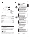
■ HOW TO ASSEMBLE
Included in the box, please nd the
following:
1) PUMP HANDLE & PUMP LEVER.
2) SPRAYER (Pump Module installed).
3) HIP SUPPORT. (Packed in tank)
4) SPARE PARTS (bag with locking pins
& washer).
5) AGITATOR (Packed in tank)
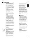
PUMP HANDLE
The pump handle is made of a tubular
steel with a plastic grip on one end, and a
round tube welded to the opposite side at
right angle. The at bar has a hole
12.5mm (1/2”) in diameter. This hole is
located 57mm (2 1/4”) from the round
tube. (See gure 1).
PUMP LEVER
The pump lever is made of a 15.2cm
(1/2’) solid round steel bar with two
bends, one on either side of the bar. (See
gure 1).
PUMP MODULE
Pump module is installed in the sprayer.
Now proceed to install pump handle and
lever.
Fig. 2
Fig. 1
Fig. 3
BP5
US-6
(2)
(3)
(1)
(1) Pump Handle
(2) Pump Lever
(3) Pump Module