


9
SETUP AND ADJUSTMENTS
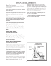
Mower Deck Leveling
Position machine on a flat surface. Preferably
level concrete.
Check the tire pressure in all four tires. Inflation
should be 15 psi.
Place 2x4’s on edge under the cutting deck from
front to rear and lower the deck down onto
2x4’s.
Adjust the four upper chain bolts to the center
slots in the deck lift arms. NOTE: Make sure the
lift blocks under the frame are tightly bolted to
the frame.
Check the chains for equal tension. If unequal
adjust upper chain bolt in slot.
Place the deck in the 5” cutting height and
measure from the cutting edge of the blade to
the flat level surface to check the deck cutting
height.
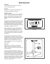
Throttle Lever Tension
Stop engine and remove key.
Throttle lever tension may be adjusted by
tightening the pivot bolt. The pivot bolt secures
the throttle arm to the mounting bracket which is
mounted to the console. Access is gained by
removing the console.
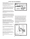
Reverse Spring Detent Adjustment
Stop engine and remove key.
Pull the motion control lever back to the reverse
position and release the lever. When the lever
stops it should be in line with the neutral slot, so
you can move the lever into neutral slot with out
hitting the side of the console frame.
If adjustment is required put the seat in the rear
most position on the slide, tilt the seat forward,
remove the seat rod from seat frame and fold
seat over forward onto the frame.
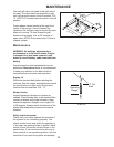
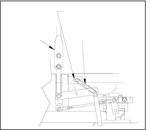
On the back of the console where the spring is
fastened, loosen the 3/8” nut and bolt enough to
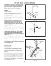
allow the bolt to slide in the slot. FIG - 6
Motion
Control
Lever
Reverse Detent
Adjustment Slot
Reverse Detent
Spring
Rotate the motion control lever out into the
neutral slot. While the lever is swung out into
the neutral slot pull it against the the back edge
of the neutral slot. Holding the lever adjust the
spring by sliding the bolt in the slot to remove
all the slop and retighten the bolt.
Check your adjustment by repeating the sec-
ond step in this process.
If no more adjustment is needed reassemble
the seat rod to the seat frame.
FIG - 6