


10
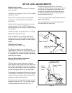
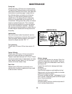
Motion Control Linkage Adjustment
This adjustment must be made with the rear
wheels rotating. Raise the rear of the machine
and block it up so the wheels are free to rotate.
CAUTION: Keep hands, feet and clothing
away from rotating tires.
Tilt seat forward and remove the seat rod so the
seat may rotate forward onto the frame.
Place a 2x4 board between the foot plate and
the center of the seat to engage the seat
safety switch.
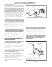
Loosen the nuts directly behind each ball joint
on both rods that connect the pump arm to the
motion control assemblies. FIG - 9
Start the engine. The park brake must be
engaged and the motion control levers in the
neutral slots to start the engine. Run the en-
gine approximately half throttle
Release park brake to allow the wheels to
rotate.
SETUP AND ADJUSTMENTS
Turn Here
To Adjust
Loosen Here
Loosen Here
(Lt. Hand Thds.)
Motion
Control
Lever
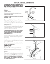
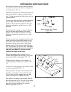
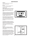
Park Brake Adjustment
When park brake is in the engaged position the
distance between the trunion and the bolt head
at the rear of the assembly should measure 1/8”
to 1/4” and the spring should measure 1.25”. To
adjust the gap between the trunion and the bolt
head loosen the nut against the yoke then turn
the bolt head the proper direction to achieve the
proper gap. To adjust the length of the spring
turn the nut against the spring the proper direc-
tion to lengthen or shorten the spring. This
adjustment is the same for both sides. FIG - 8
• If brake lever trys to catch as you engage the
brake the spring needs to be tightened. When
you change the spring length you also have to
maintain the 1/8” to 1/4” gap between the bolt
head and the trunion.
NOTE: Do not force the brake lever into the on
position if it is catching this will cause damage
to the brake assembly.
• If brake squeaks while the machine is in use.
The spring may be to tight or the gap between
the bolt head and the trunion may be to large.
Loosen here
1/4” Gap
Spring
FIG - 8
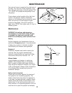
FIG - 9
Begin with either side and put the motion control
lever into the neutral position. Adjust the motion
control linkage by rotating the double nuts in the
proper direction until the wheel stops rotating.
FIG - 9 Move the motion control lever forward
then into the neutral position and place it into the
neutral slot. The wheel must be stopped com-
pletely at this point. Now do the same in reverse
and release the lever. The lever should return to
neutral on its own. If not see reverse spring
detent adjustment.