


4
ASSEMBLY
Read these instructions and this man u al in its entirety before you attempt to assemble or operate your new lawn mow er.
IMPORTANT: THIS LAWN MOWER IS SHIPPED WITH OUT OIL OR GASOLINE IN THE ENGINE.
Your new lawn mower has been as sem bled at the factory with the ex cep tion of those parts left unassembled for shipping
purposes. All parts such as nuts, washers, bolts, etc., necessary to com plete the as sem bly have been placed in the parts
bag. To ensure safe and proper operation of your lawn mow er, all parts and hard ware you assemble must be tightened
se cure ly. Use the correct tools as nec es sary to ensure proper tightness.
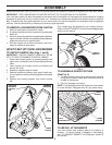
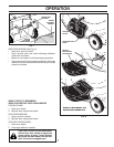
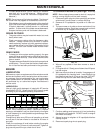
TO ASSEMBLE GRASS CATCHER
(See Fig. 3)
1. Put grass catcher frame into grass bag with rigid part
of bag on the bottom. Make sure the frame handle is
outside of the bag top.
2. Slip vinyl bindings over frame.
NOTE: If vinyl bindings are too stiff, hold them in warm water
for a few minutes. If bag gets wet, let it dry before using.
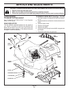
TO INSTALL ATTACHMENTS
Your lawn mower was shipped ready to be used as a
mulcher. To convert mower to bagging or discharging,
see “TO CON VERT MOWER” in the Operation section of
this man u al.
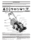
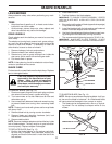
FIG. 1
OPERATOR
PRESENCE
CONTROL
BAR
HANDLE
KNOB
LIFT
UP
LIFT
UP
LOWER
HANDLE
MOWING
PO SI TION
UPPER
HANDLE
FIG. 3
FRAME
HANDLE
VINYL
BINDINGS
FRAME
OPENING
TO RE MOVE LAWN MOW ER FROM CAR TON
1. Remove loose parts included with mower.
2. Cut down two end corners of car ton and lay end panel
down fl at.
3. Remove all packing materials ex cept padding be tween
upper and lower handle and padding holding operator
presence control bar to up per handle.
4. Roll lawn mower out of carton and check carton thor-
ougly for ad di tion al loose parts.
HOW TO SET UP YOUR LAWN MOW ER
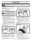
TO UNFOLD HANDLE (See Figs. 1 and 2)
IMPORTANT: UNFOLD HANDLE CAREFULLY SO AS
NOT TO PINCH OR DAMAGE CON TROL CABLES.
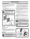
1. Raise lower handle section to operating position and
align hole in handle with one of three height positioning
holes.
2. Insert handle bolt through handle and bracket and
secure with knob.
3. Repeat for opposite side of handle.
4. Remove protective padding, raise upper handle sec-
tion into place on lower handle and tighten both handle
knobs.
5. Remove any packing material from around control
bar.
Your handles may be adjusted for your mowing comfort.
Refer to “ADJUST HANDLE” in the Service and Ad just ments
sec tion of this man u al.
FIG. 2
HANDLE
BRACKET
BOLT
KNOB