


15
CAUTION: TO AVOID SERIOUS INJURY, BEFORE
PERFORMING ANY SERVICE OR ADJUSTMENTS:
1. Release control bar and stop engine.
2. Make sure the blade and all moving parts
have completely stopped.
3. Disconnect spark plug wire from spark
plug and place where it cannot come in
contact with plug.
LAWN MOWER
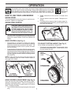
TO ADJUST CUTTING HEIGHT
See “TO ADJUST CUTTING HEIGHT” in the Operation
section of this manual.
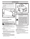
REAR DEFLECTOR
The rear defl ector, attached between the rear wheels of
your mower, is provided to minimize the possibility that
objects will be thrown out of the rear of the mower into
the operator's mowing position. If the defl ector becomes
damaged, it should be replaced.
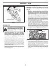
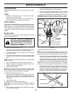
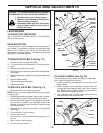
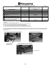
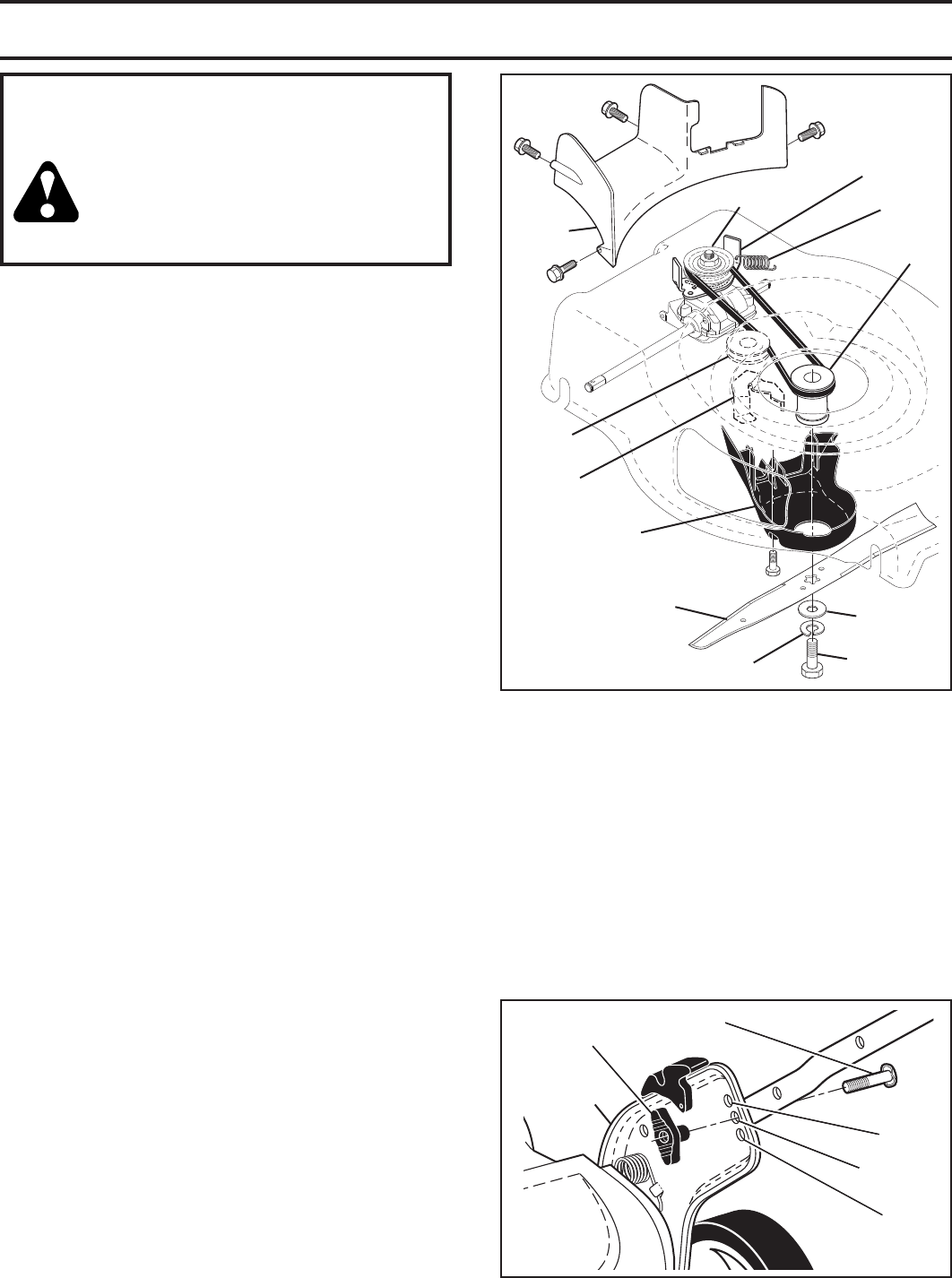
TO REMOVE DRIVE BELT (See Fig. 19)
1. Remove screws securing rear baffl e.
2. Turn lawn mower on its side with air fi lter and car bu re-
tor up.
3. Remove rear baffl e from mower.
4. Disconnect return spring from rear baffl e / rear gearcase
belt keeper.
5. Remove blade bolt, lockwasher, hardened washer and
blade.
6. Remove debris shield.
7. Remove gearcase belt keeper.
8. Remove drive belt.
TO REPLACE DRIVE BELT (See Fig. 19)
1. Place new drive belt on gearcase pulley.
NOTE: Always use factory approved belt to assure proper
fi t and long life.
2. Reinstall gearcase belt keeper. Be sure the new drive
belt is inside the tabs of the gearcase belt keeper.
3. Position the blade adapter on the engine crank shaft.
Be sure key in adapter and crankshaft keyway are
aligned; and that the new drive belt is inside the tabs
of the belt retainer.
4. Reattach return spring to rear baffl e / rear gearcase
belt keeper.
5. Place rear baffl e in mower housing.
6. Reinstall debris shield.
7. Reinstall blade. The recommended tightening torque is 33-
40 ft. lbs.
8. Return mower to upright po si tion.
9. Reinstall rear baffl e screws.
SERVICE AND ADJUSTMENTS
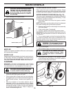
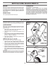
FIG. 20
HANDLE
BRACKET
BOLT
KNOB
HIGH
MEDIUM
LOW
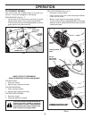
TO ADJUST HANDLE (See Fig. 20)
The handle on your lawn mower has three (3) height posi-
tions - adjust to height that suits you.
1. Remove knob and carriage bolt on one side of the
lower handle.
2. While holding handle assembly, remove knob and
car riage bolt from opposite side, align hole in handle
with desired hole in handle bracket and reassemble
bolt and knob and tighten securely.
3. Align opposite side of handle with same positioning
hole and secure with bolt and knob.
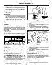
FIG. 19
BLADE BOLT
HARDENED
WASHER
LOCKWASHER
BLADE
ADAPTER
BLADE
BELT
RETAINER
IDLER
PULLEY
RETURN
SPRING
GEARCASE
BELT KEEPER
DEBRIS
SHIELD
REAR
BAFFLE
GEARCASE
PULLEY