


6
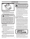
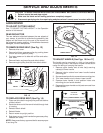
TO CONVERT MOWER
Your lawn mower was shipped ready to be used as a
mulcher. To convert to bagging or discharging:
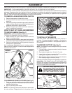
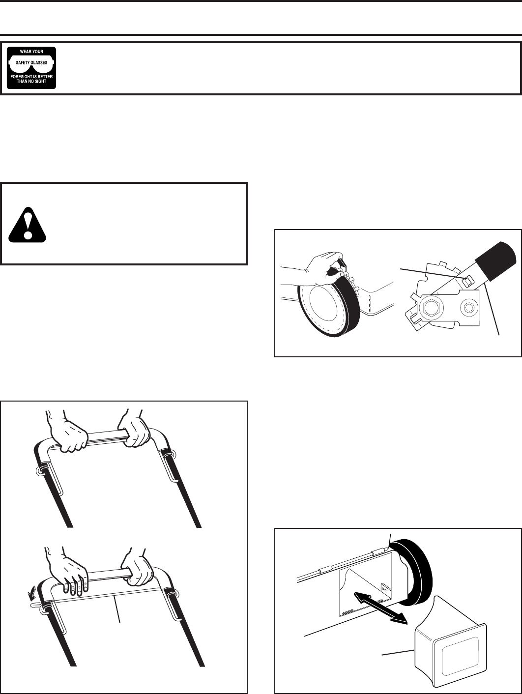
REAR BAGGING (See Fig. 6)
• Open rear door and remove mulcher plug. Store
mulcher plug in a safe place.
• You can now install the grass catcher or optional clip-
ping deflector.
• To convert to mulching or discharging operation, install
mulcher plug into rear discharge opening of mower.
HOW TO USE YOUR LAWN MOWER
ENGINE SPEED
The engine speed was set at the factory for optimum per-
formance. Speed is not adjustable.
ENGINE ZONE CONTROL
CAUTION: Federal regulations require
an engine control to be installed on this
lawn mower in order to minimize the risk
of blade contact injury. Do not un der
any cir cum stanc es attempt to defeat
the function of the operator control. The
blade turns when the engine is running.
• Your lawn mower is equipped with an operator pres-
ence control bar which requires the operator to be
positioned behind the mower handle to start and
operate the mower.
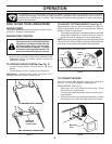
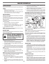
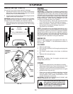
TO OPERATE DRIVE SYSTEM (See Fig. 4)
• To start forward motion, lift drive control bar up to
handle.
• To stop forward motion, release drive control bar.
IMPORTANT: ALWAYS KEEP DRIVE CONTROL FULLY
ENGAGED AGAINST HANDLE WHEN IN USE.
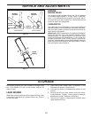
The operation of any lawn mower can result in foreign objects thrown into the eyes, which can result
in severe eye damage. Always wear safety glasses or eye shields while operating your lawn mower or
performing any adjustments or repairs. We recommend standard safety glasses or a wide vision safety
mask over spectacles.
OPERATION
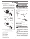
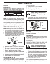
TO ADJUST CUTTING HEIGHT (See Fig. 5)
Raise wheels for low cut and lower wheels for high cut,
adjust cutting height to suit your requirements. Me di um
position is best for most lawns.
• To change cutting height, squeeze adjuster lever to ward
wheel. Move wheel up or down to suit your re quire -
ments. Be sure all wheels are in the same setting.
NOTE: Adjuster is properly positioned when plate tab inserts
into hole in lever. Also, 9-position adjusters (if so equipped)
allow lever to be positioned between the plate tabs.
MULCHER
PLUG
FIG. 6
FIG. 5
LEVER BACKWARD TO LOWER MOWER
LEVER FORWARD TO RAISE MOWER
PLATE
TAB
LEVER
OPERATOR
PRES ENCE
CON TROL BAR
DRIVE CONTROL DISENGAGED
TO ENGAGE DRIVE CONTROL
FIG. 4