


7
ASSEMBLY
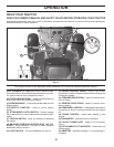
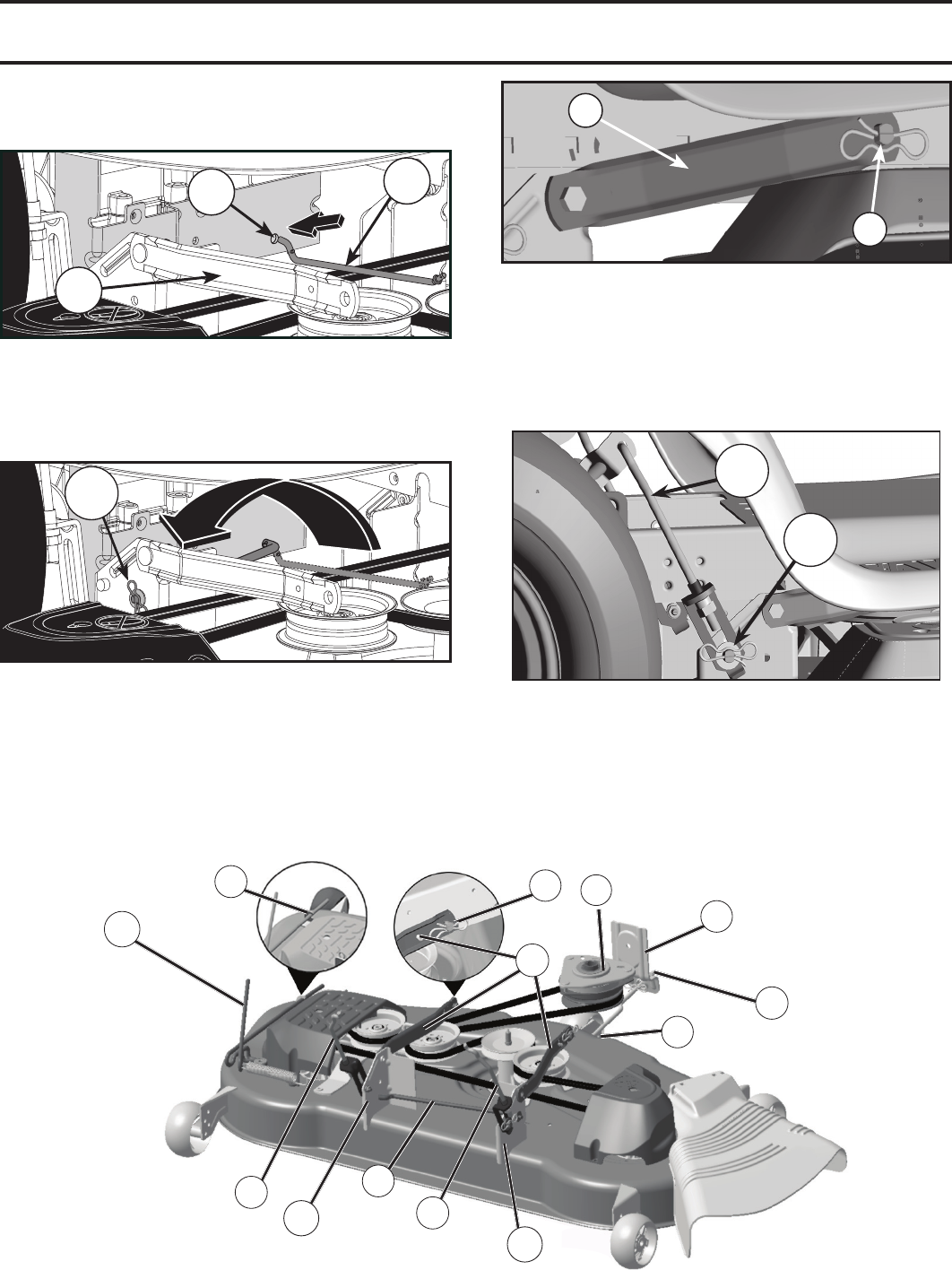
Fig. 10
B
F
M
C
S
E
K
D
L
D
A
C
H
D
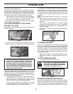
Fig. 7
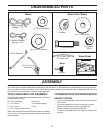
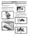
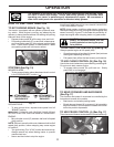
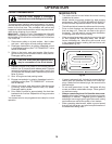
• FIRST INSTALL ANTI-SWAY BAR (S).
• From right side of mower, insert anti-sway bar into
hole in transmission bracket (T).
Fig. 6
• Pivot bar towards you and insert other end of bar
into hole in rear mower bracket (D). Move mower
as needed to insert bar.
• Secure with washer and retainer spring as shown
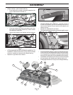
• ATTACH MOWER SIDE SUSPENSION ARMS (A) TO
CHASSIS - Position hole in arm over pin (B) on outside
of tractor chassis and secure with retainer spring.
• Repeat on opposite side of tractor.
Fig. 8
A
B
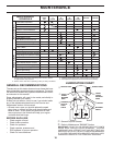
• ATTACH REAR LIFT LINKS (C) - Lift rear corner of
mower and position slot in link assembly over pin on
rear mower bracket (D) and secure with washer and
retainer spring.
• Repeat on opposite side of tractor.
• Turn steering wheel to position wheels straight forward.
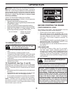
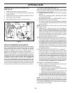
• ATTACH FRONT LINK (E) - Work from left side of tractor.
Insert rod end of link assembly through front hole in trac-
tor front suspension bracket (F) and secure with retainer
spring (G) through hole in link located behind the bracket.
• Insert other end of link (E) into hole in front mower bracket
(H) and secure with washer and retainer spring (J).
• Disengage belt tension rod (K) from locking bracket (L).
S
T
A
Fig. 9
D
C
D
C