


6
ASSEMBLY / PRE-OPERATION
Read these instructions and this manual in
its entirety before you attempt to assemble
or operate your new lawn mower.
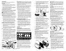
IMPORTANT: This lawn mower is shipped
WITHOUT OIL OR GASOLINE in the engine.
Your new lawn mower has been as-
sem bled at the factory with the excep-
tion of those parts left unassembled for
shipping pur pos es. To ensure safe and
proper op er a tion of your lawn mower, all
parts and hard ware you assemble must be
tight ened securely. Use the correct tools
as nec es sary to ensure proper tightness.
All parts such as nuts, wash ers, bolts, etc.,
nec es sary to complete the as sem bly have
been placed in the parts bag.
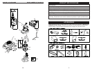
TO REMOVE LAWN MOWER FROM
CARTON
1. Remove loose parts included with
mower.
2. Cut down two end corners of carton
and lay end panel down fl at.
3. Remove all packing materials except
padding be tween upper and lower
handle and padding holding operator
presence control bar to upper handle.
4. Roll lawn mower out of carton and
check carton thor ough ly for additional
loose parts.
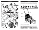
HOW TO SET UP YOUR LAWN
MOW ER
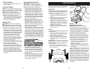
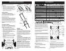
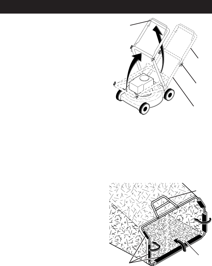
TO UNFOLD HANDLE
IMPORTANT: Unfold handle carefully so
as not to pinch or damage con trol cables.
1. Raise handles until lower handle sec-
tion locks into place in mowing position.
2. Remove protective padding, raise up-
per handle sec tion into place on lower
handle and tighten both handle knobs.
3. Remove handle padding holding
operator pres ence control bar to upper
handle.
Your lawn mower handle can be adjusted
for your mowing comfort. Refer to “AD-
JUST HANDLE” in the Service and Adjust-
ments section of this manual.
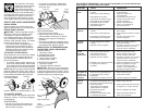
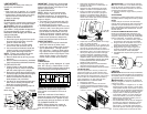
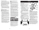
TO ASSEMBLE GRASS CATCH ER
1. Put grass catcher frame into grass bag
with rigid part of bag on the bottom.
Make sure the frame handle is outside
of the bag top.
2. Slip vinyl bindings over frame.
NOTE: If vinyl bindings are too stiff, hold
them in warm water for a few minutes. If
bag gets wet, let it dry before using.
TO INSTALL ATTACHMENTS
Your lawn mower was shipped ready to
be used as a mulcher. To convert to bag-
ging or discharging, see “TO CON VERT
MOWER” in the Operation section of this
manual.
Frame
handle
Frame
opening
Vinyl
bindings
MOWING
POSITION
Lower handle
LIFT
UP
Operator
presence
control bar
Upper
handle
LIFT
UP
Handle
knob
35
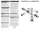
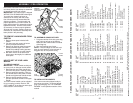
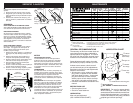
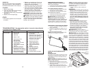
HUSQVARNA ROTARY LAWN MOWER - - MODEL NUMBER 917.384510 (PRODUCT NUMBER 6021P)
KEY PART
NO. NO. DESCRIPTION
KEY PART
NO. NO. DESCRIPTION
1 194177X422 Control Bar
2 197808 Upper Handle
3 169708X498 Lower Handle
4 194788 Rope Guide
5 132004 Nut, Hex
6 191574 Handle Bolt
7 66426 Wire Tie
8 74780512 Bolt, Hex Head 5/16-18 x 3/4
9 154132 Hinge Bracket
10 185589 Mulcher Door
11 183281 Engine Zone Control Cable
12 750634 Hex Washer Head Screw
13 429930X004 Up-Stop Bracket
14 182398 Handle Knob
15 51793 Hairpin Cotter
18 17600406 Screw 1/4-20 x 3/8
19 401174X004 Axle Arm Assembly, Front, LH
20 401175X004 Axle Arm Assembly, Front, RH
21 418655 Kit, Rear Skirt
22 401621X004 Selector Spring, Front
23 401814X428 Rear Door Assembly
25 410385X422 Handle Bracket Assembly, LH
26 410386X422 Handle Bracket Assembly, RH
29 407494X005 Wheel Adjusting Bracket
30 401629 Spacer
31 185595 Discharge Defl ector
32 401624X004 Selector Spring, Rear
33 87877 Selector Knob
34 401176X004 Axle Arm Assembly, Rear, LH
35 426589 Locknut, Hex 5/16-18
36 401638 Shoulder Bolt 5/16-18
37 401273X460 Wheel & Tire Assembly, Front
39 409149 Flanged Locknut, Hex
40 411949 Frame, Grassbag
41 88652 Hinge Screw
42 405421 Spring, Rear Door, LH
43 405423 Spring, Rear Door, RH
44 184193 Bolt, Rear Door
45 150406 Screw, Hex Head, Threaded,
Rolled 3/8-16 x 1
46 404763 Danger Decal
47 751153 Nut, Hex
48 401177X004 Axle Arm Assembly, Rear, RH
49 401277X460 Wheel & Tire Assembly, Rear
50 194715 Grassbag
51 147286 Hinge Rod
52 418709 Kit, Housing
(Includes Key Number 46)
53 851084 Screw, Hex Head, Grade 8
3/8-24 x 1-3/8
54 850263 Helical Lockwasher
55 851074 Hardened Washer
NOTE: All component dimensions given in U.S. inches. 1 inch = 25.4 mm
IMPORTANT: Use only Original Equipment Manufacturer (O.E.M.) replacement parts. Failure to do so could be hazardous, damage your lawn mower and void your warranty.
56 406712 21" Blade
57 420097 Blade Adapter
58 152124 Hinge Spring
59 - - - Engine, Kohler, Model
Number XT149-0026-EA
(See Breakdown)
61 409148 Nut, Hex
62 73800400 Locknut, Hex 1/4-20
65 88348 Washer, Flat
66 197480 O-Ring
67 197991 Clip, Cable
68 164265 Grip, Foam
73 401630 Washer, Curved
74 851201X004 Washer, Special, Engine
75 413693 Kit, Rear Baffl e
(Includes 3 Screws)
76 410589 Baffl e, Rear
77 17411312 Screw, Rear Baffl e
- - 404764 Warning Decal (not shown)
- - 431621 Owner’s Manual
Available accessories not included with mower:
- - 71 33623 Gas Can
(2.5 Gallon Container)
- - 71 33500 Fuel Stabilizer
- - 71 33000 SAE 30W Oil
(20 Ounce Bottle)
KEY PART
NO. NO. DESCRIPTION