


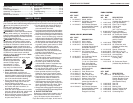
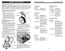
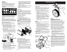
6
ASSEMBLY / PRE-OPERATION
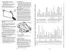
TO ASSEMBLE GRASS CATCH ER
1. Put grass catcher frame into grass bag
with rigid part of bag on the bottom.
Make sure the frame handle is outside
of the bag top.
2. Slip vinyl bindings over frame.
NOTE: If vinyl bindings are too stiff, hold
them in warm water for a few minutes. If
bag gets wet, let it dry before using.
TO INSTALL ATTACHMENTS
Your lawn mower was shipped ready to be
used as a mulcher. To convert mower to
bagging or discharging, see “TO CON-
VERT MOWER” in the Operation section
of this manual.
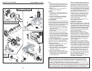
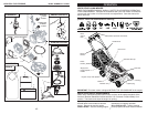
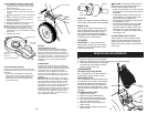
Frame
handle
Frame
opening
Vinyl
bindings
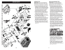
MOWING
POSITION
Lower handle
LIFT
UP
Operator
presence
control bar
Upper
handle
LIFT
UP
Handle
knob
Read these instructions and this man u al in its entirety before you attempt to assemble
or operate your new lawn mower.
IMPORTANT: This lawn mower is shipped WITHOUT OIL OR GASOLINE in the engine.
Your new lawn mower has been as sem bled at the factory with the ex cep tion of those
parts left unassembled for shipping purposes. All parts such as nuts, washers, bolts, etc.,
necessary to com plete the as sem bly have been placed in the parts bag. To ensure safe
and proper operation of your lawn mow er, all parts and hard ware you assemble must be
tightened se cure ly. Use the correct tools as necessary to ensure proper tightness.
Handle
bracket
Handle pin
SQUEEZE
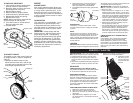
TO RE MOVE MOW ER FROM CAR TON
1. Remove loose parts included with
mower.
2. Cut down two end corners of carton
and lay end panel down fl at.
3. Remove all packing materials ex cept
padding be tween upper and lower
handle and padding holding operator
presence control bar to upper handle.
4. Roll lawn mower out of carton and
check carton thorougly for ad di tion al
loose parts.
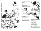
HOW TO SET UP YOUR MOW ER
TO UNFOLD HANDLE
IMPORTANT: Unfold handle carefully so
as not to pinch or damage con trol cables.
1. Raise lower handle section to operat-
ing position and squeeze the bottom
ends of lower handle towards each
other until the pin in handle can be
inserted into one of the three height
adjustment holes.
2. Remove protective padding, raise up-
per handle sec tion into place on lower
handle and tighten both handle knobs.
3. Remove any packing material from
around control bar.
Your lawn mower handle can be adjusted
for your mowing comfort. Refer to “AD-
JUST HANDLE” in the Service and Adjust-
ments section of this manual.
43
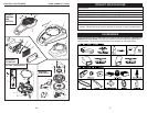
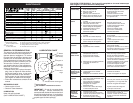
MODEL NUMBER XT173-0084
KOHLER 4-CYCLE ENGINE
CRANKSHAFT
KEY PART
NO. NO. DESCRIPTION
1 14 014 14-S Crankshaft Assembly
2 14 340 01-S Key, Flywheel
GASKET SET
KEY PART
NO. NO. DESCRIPTION
1 14 153 01-S O-Ring, Dipstick
2 14 153 03-S O-Ring, Oil Fill Tube
3 14 032 04-S Seal, Oil
4 14 841 04-S Kit, Head Gasket
(Includes Key Number 6
and Muffl er Gasket)
5 14 041 01-S Gasket, Valve Cover
6 14 041 05-S Kit, Carburetor Gasket
(Includes Carburetor
Heat Shield Gasket
and Air Cleaner Base
Gasket)
7 14 041 06-S Gasket, Oil Pan
8 14 032 05-S Seal, Oil (PTO)
Not Illustrated:
- - 14 755 01-S Gasket Set (Includes
Key Numbers 1–8,
Muffl er Gasket, Breather
Cover Gasket, Valve
Stem Seal and Crank-
case / Flywheel Seal)
DECALS
KEY PART
NO. NO. DESCRIPTION
1 14 450 02-S Hang Tag, Maintenance
2 14 113 03-S Decal, Warning
3 41 037 10-S Nameplate, Service
ENGINE CONTROLS
KEY PART
NO. NO. DESCRIPTION
1 14 089 07-S Spring, Linkage
2 14 090 12-S Lever, Governor
3 M-641060-S Nut, Flanged, M6 x 1.0
4 14 126 22-S Control Assembly,
Fixed Speed
5 14 089 14-S Spring, Governor
(2800-3300 RPM)
6 25 086 166-S Screw, Rectangle
Head (M6)
STARTING SYSTEM
KEY PART
NO. NO. DESCRIPTION
1 14 165 01-S Starter, Recoil (Includes
Key Numbers 3 and 4,
Recoil Housing, Recoil
Bushing, Recoil Guide
Plate, Recoil Springs,
Recoil Pulley, Recoil
Retainer Plate and
Recoil Shoulder Screw)
2 M-641060-S Nut, Flanged, M6 x 1.0
3 14 160 01-S Kit, Starter Rope, with
Handle (Includes Coil
Starter Rope, Recoil
Starter Handle, Recoil
Starter Handle Retainer,
Recoil Rope Retainer)
4 14 379 01-S Kit, Pawl Repair
(Includes Recoil Springs,
Recoil Starter Pawls)