


15
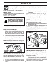
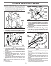
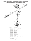
TO REMOVE DRIVE BELT (See Figs. 18 thru 21)
1. Disconnect spark plug wire from spark plug and place
wire where it cannot come in contact with spark plug.
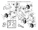
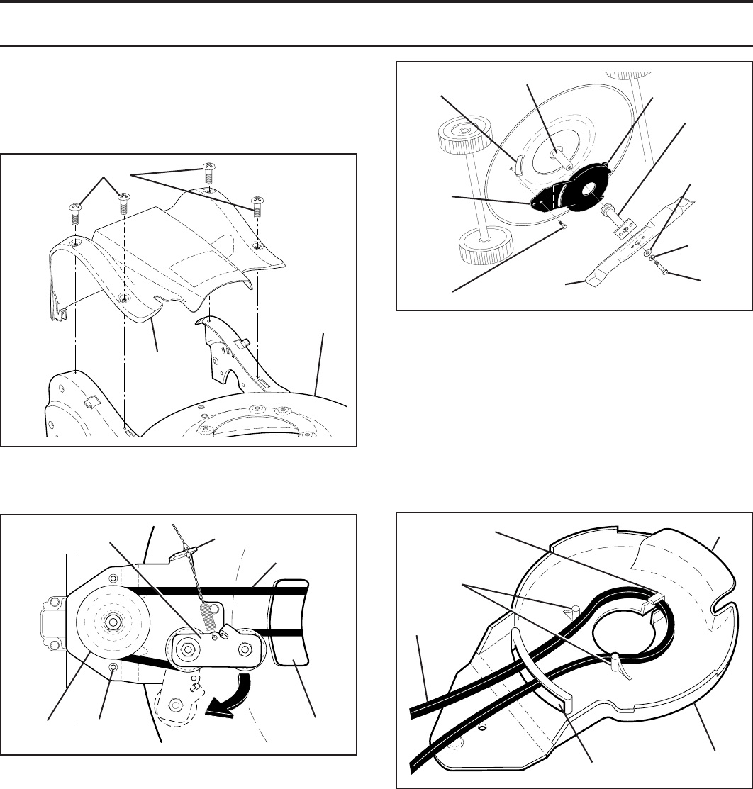
2. Remove screws retaining drive cover and remove drive
cover from lawn mower housing (See Fig. 18).
SERVICE AND ADJUSTMENTS
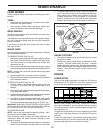
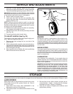
9. Remove blade, attaching hardware (bolt, lock wash er,
hardened wash er), blade adapter and debris shield as
one assembly.
10. Remove drive belt from blade adapter and debris shield;
discard old belt.
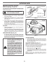
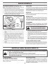
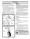
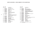
TO REPLACE DRIVE BELT (See Figs. 18–21)
1. Place new drive belt in the belt retainer of the debris
shield. Be sure to route belt between belt keepers and
through slot (See Fig. 21).
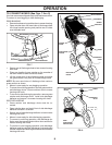
DRIVE CABLE ANCHOR
IDLER ARM ASSEMBLY
BELT
KEEPER
DRIVE
PULLEY
HOUSING
HOLE
PIVOT
DRIVE BELT
FIG. 19
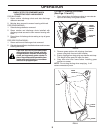
TRAILING
EDGE
CRANKSHAFT
DEBRIS
SHIELD
SCREW
BLADE
ADAPTER
HARDENED
WASHER
LOCK-
WASHER
BLADE
BOLT
TAB
HOUSING
HOLE
FIG. 20
DEBRIS
SHIELD
BELT RETAINER
BELT
KEEPERS
DRIVE
BELT
SLOT
TAB
FIG. 21
SCREWS
DRIVE
COVER
LAWN
MOWER
HOUSING
FIG. 18
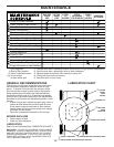
3. Remove drive cable from anchor, then detach the drive
cable spring from idler arm assembly (See Fig. 19).
4. Pivot idler arm assembly to slacken drive belt, then
remove drive belt from drive pulley, belt keepers and
idler arm.
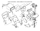
5. Turn lawn mower on its side. Make sure air fi lter and
carburetor are up.
6. Remove screw securing debris shield. Note that the
debris shield has a tab which fi ts into a gap in the
housing (See Fig. 20).
7. Use a wood block between blade and mower hous ing
to prevent blade from turning when re mov ing blade
bolt.
NOTE: Protect your hands with gloves and/or wrap blade
with heavy cloth.
8. Remove blade bolt.
2. Route the other end of the new drive belt through hole
in housing.
3. Reattach debris shield to housing with screw previ-
ously removed. Be sure tab of debris shield is in gap
of housing.
4. Position blade on the blade adapter aligning the two
(2) holes in the blade with the raised lugs on the
adapter.
5. Be sure the trailing edge of blade (opposite sharp edge)
is up toward the engine (See Fig. 20).
6. Install the blade bolt with the lock washer and hardened
washer into blade adapter and crankshaft.