


8
The operation of any
lawn mower can result
in foreign objects thrown
into the eyes, which can
result in severe eye dam-
age. Always wear safety glasses or eye
shields while operating your lawn mower
or performing any ad just ments or repairs.
We recommend a standard safety glasses
or wide vision safety mask worn over
spectacles.
HOW TO USE YOUR LAWN MOWER
ENGINE SPEED
Engine speed was set at the factory for
optimum performance. It is not adjustable.
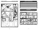
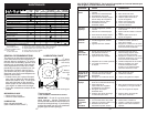
ENGINE ZONE CONTROL
CAUTION: Federal regulations re quire
an engine control to be installed on this
lawn mower in order to minimize the risk
of blade contact injury. Do not un der
any circumstances attempt to de feat the
func tion of the operator con trol. The blade
turns when the engine is running.
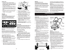
• Your lawn mower is equipped with an
operator pres ence control bar which
requires the operator to be positioned
behind the lawn mower handle to start
and operate the lawn mower.
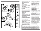
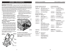
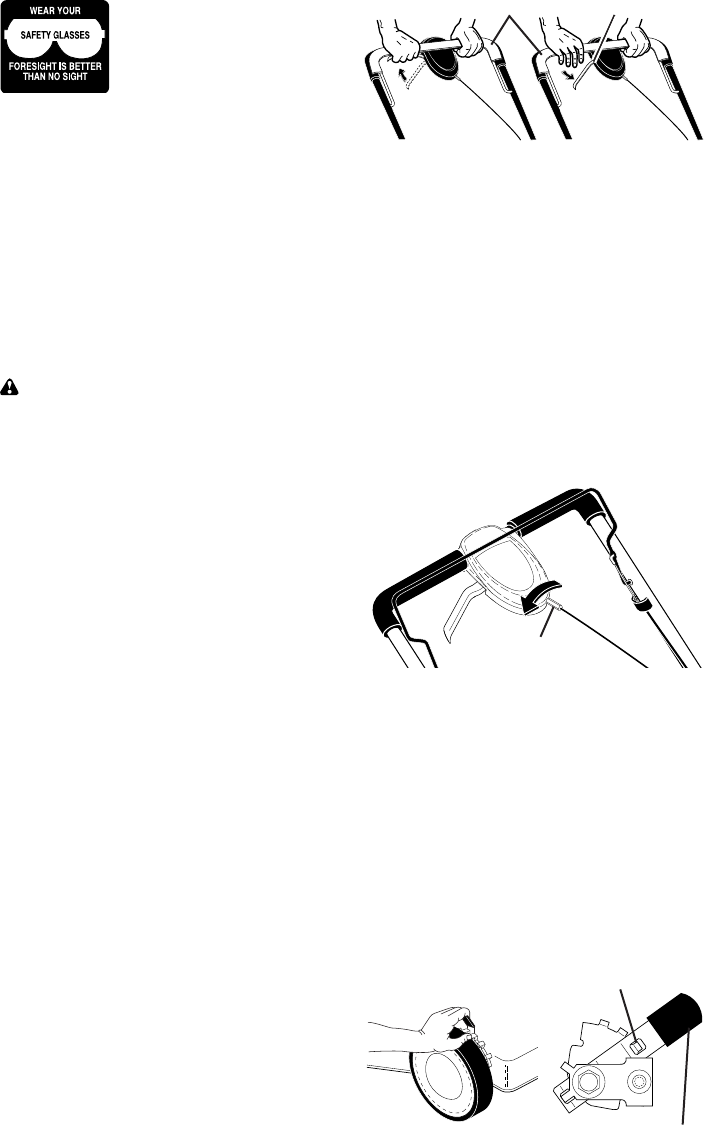
DRIVE CONTROL
• Self-propelling is controlled by hold-
ing the operator presence control bar
down to the handle and pulling the drive
control lever rearward to the handle.
The farther toward the handle the lever
is pulled, the faster the unit will travel.
• Forward motion will stop when either
the operator presence control bar or
drive control lever are released. To stop
forward motion without stop ping engine,
re lease the drive control lever only. Hold
op er a tor presence control bar down
against handle to con tin ue mowing
without self-propelling.
NOTE: If after releasing the drive control
the mower will not roll backwards, push
the mower forward slightly to disengage
drive wheels.
• To keep drive control engaged when
turning corners, push down on the
handle to lift the front wheels off the
ground while turning lawn mower.
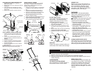
LEVER BACKWARD
TO LOWER MOWER
LEVER FORWARD TO RAISE MOWER
Plate tab
Lever
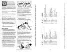
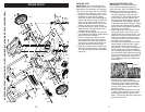
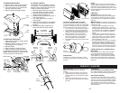
DRIVE CONTROL ADJUSTMENT
Over time, the drive control system may
become “loose”, resulting in decreased
speed. There is a turnbuckle on the
un der side of the drive control housing to
increase tension on the drive cable. Pro-
ceed as follows:
1. Turn unit off and disconnect spark plug
wire from spark plug.
2. Turn nut on underside of drive control
to increase drive speed.
3. Operate mower to test drive speed.
Readjust as required.
4. If condition fails to improve after the
above steps (forward speed remains
the same), your drive belt is worn and
should be re placed.
TO ADJUST CUTTING HEIGHT
Raise wheels for low cut and lower wheels
for high cut, adjust cutting height to suit
your requirements. Me di um position is
best for most lawns.
• To change cutting height, squeeze ad-
juster lever to ward wheel. Move wheel
up or down to suit your re quire ments. Be
sure all wheels are in the same setting.
NOTE: Adjuster is properly positioned
when plate tab inserts into hole in lever.
Also, 9-position adjusters (if so equipped)
allow lever to be positioned between the
plate tabs.
Adjustment
turnbuckle
TO
ENGAGE
DRIVE
CONTROL
Drive control
lever
DRIVE
CONTROL
DISENGAGED
Operator presence control bar
41
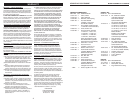
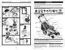
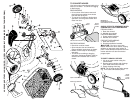
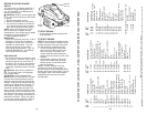
HUSQVARNA ROTARY LAWN MOWER - - MODEL NUMBER 917.374080 (PRODUCT NUMBER 7021)
NOTE: All component dimensions given in U.S. inches. 1 inch = 25.4 mm.
IMPORTANT: Use only Original Equipment Manufacturer (O.E.M.) replacement parts. Failure to do so could be hazardous, damage your lawn mower and void your warranty.
KEY PART
NO. NO. DESCRIPTION
KEY PART
NO. NO. DESCRIPTION
1 425580 Drive Control Assembly (Includes Cable)
2 406260X460 Cover, Top
3 406262 Pulley
4 425538 Lever, Drive Control
5 406261X460 Cover, Bottom
6 181698 Screw
7 400235X479 Mounting Bracket
9 406259 Cable Assembly, Drive Control
11 401274X460 Wheel & Tire Assembly
12 12000058 E-Ring
13 403849 Gear, Pinion
14 189403 Dust Cover
15 404845 Pawl, Drive
16 67725 Washer 1/2 x 1-1/2 x .134
17 191039 Bearing, Wheel Adjuster
18 701037 Selector Knob
25 404843X004 Belt Keeper
26 163409 Screw, Hi-Lo Thread #12 x 5/8
27 175262 Pan Head Tapping Screw #10-24 x 2-3/4
28 194406X418 Drive Cover
29 194149 V-Belt
32 194018 Pulley, Drive
33 409148 Locknut, Hex
35 408862 Kit, Wheel Adjuster, LH
(Includes Knob and Bearing)
36 404833 Gear Case Assembly, Complete
38 73800400 Locknut, Hex 1/4-20
40 406558 Spring
41 408861 Kit, Wheel Adjuster, RH
(Includes Knob and Bearing)
54 425732 Grassbag
57 411950 Frame, Grassbag