


22
SERVICE AND ADJUSTMENTS
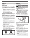
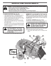
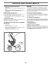
Fig. 32
RE TAIN ING
RING
WASH ERS
SQUARE KEY (REAR
WHEEL ONLY)
AXLE COVER
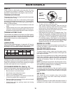
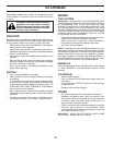
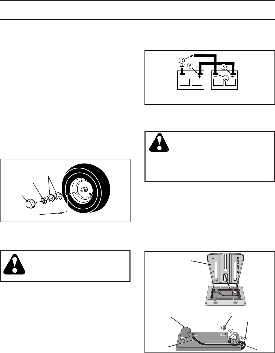
TO START ENGINE WITH A WEAK BATTERY
(See Fig. 33)
WARNING: Lead-acid batteries gen-
er ate ex plo sive gases. Keep sparks,
flame and smoking ma te ri als away from
bat ter ies. Always wear eye pro tec tion
when around batteries.
If your battery is too weak to start the engine, it should be
recharged. (See "BATTERY" in the MAINTENANCE sec-
tion of this man u al).
If “jumper ca bles” are used for emer gen cy starting, follow
this pro ce dure:
IMPORTANT: YOUR TRACTOR IS EQUIPPED WITH A 12 VOLT
SYSTEM. THE OTHER VEHICLE MUST ALSO BE A 12 VOLT
SYSTEM. DO NOT USE YOUR TRACTOR BATTERY TO START
OTHER VEHICLES.
TO ATTACH JUMPER CABLES -
• Connect one end of the RED cable to the POSITIVE
(+) terminal of each battery(A-B), taking care not to
short against tractor chassis.
• Connect one end of the BLACK ca ble to the NEGA TIVE
(-) terminal (C) of fully charged battery.
• Connect the other end of the BLACK cable (D) to good
chassis ground, away from fuel tank and bat tery.
WEAK OR DEAD
BATTERY
FULLY CHARGED
BATTERY
TO REMOVE WHEEL FOR REPAIRS
(See Fig. 32)
• Block up axle securely.
• Remove axle cover, retaining ring and washers to allow
wheel removal (rear wheel contains a square key - Do
not lose).
• Repair tire and reassemble.
• On rear wheels only: align grooves in rear wheel hub
and axle. Insert square key.
• Replace washers and snap retaining ring securely in
axle groove.
• Replace axle cover.
NOTE: To seal tire punctures and prevent flat tires due
to slow leaks, tire sealant may be purchased from your
local parts dealer. Tire sealant also prevents tire dry rot
and corrosion.
Fig. 33
FRONT WHEEL TOE-IN/CAMBER
Your new tractor front wheel toe-in and camber is set at the
factory and is normal. The front wheel toe-in and camber
are not adjustable. If damage has occurred to affect the
factory set front wheel toe-in or camber, contact a qualified
service center.
TO REMOVE CABLES, REVERSE ORDER -
• BLACK cable first from chassis and then from the fully
charged battery.
• RED cable last from both batteries.
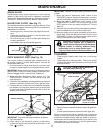
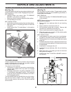
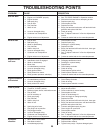
REPLACING BATTERY (See Fig. 34)
WARNING: Do not short battery
ter mi nals by allowing a wrench or any
other object to contact both terminals
at the same time. Before connecting
battery, remove metal bracelets,
wristwatch bands, rings, etc. Positive
terminal must be connected first to
prevent sparking from ac ci den tal
grounding.
• Lift seat pan to raised position.
• Disconnect BLACK battery cable first then RED battery
cable and carefully remove battery from tractor.
• Install new battery with terminals in same position as
old battery.
• First connect RED battery cable to positive (+) terminal
with bolt and nut as shown. Tighten securely. Slide
terminal cover over terminal.
• Connect BLACK grounding cable to negative (-) ter-
mi nal with remaining bolt and nut. Tighten se cure ly.
• Lower seat pan.
02603
SEAT PAN
NUT
POSITIVE
(RED)
CABLE
NEGATIVE
(BLACK)
CABLE
BOLT
TERMINAL
COVER
Fig. 34