


7
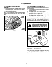
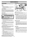
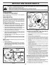
DRIVE CONTROL ADJUSTMENT (See Fig. 5B)
Over time, the drive control system may become “loose”,
resulting in decreased speed. There is a turnbuckle on the
underside of the drive control housing to increase tension
on the drive cable. Pro ceed as follows:
1. Turn unit off and disconnect spark plug wire from plug.
2. Turn nut on underside of drive control to increase drive
speed.
3. Operate mower to test drive speed. Readjust as re-
quired.
4. If condition fails to improve after the above steps (for-
ward speed remains the same), your drive belt is worn
and should be re placed.
HOW TO USE YOUR LAWN MOWER
ENGINE SPEED
The engine speed was set at the factory for optimum per-
formance. Speed is not adjustable.
ENGINE ZONE CONTROL
CAUTION: Federal regulations require
an engine control to be installed on this
lawn mower in order to minimize the risk
of blade contact injury. Do not un der
any cir cumstances attempt to defeat
the function of the operator control.
The blade turns when the engine is
running.
• Your lawn mower is equipped with an operator presence
control bar which requires the operator to be positioned
behind the lawn mower handle to start and operate the
lawn mower.
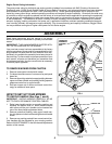
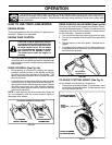
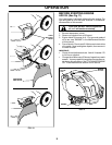
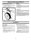
DRIVE CONTROL (See Fig. 5A)
• Self-propelling is controlled by hold ing the operator
presence control bar down to the handle and pulling
the drive control lever rearward to the handle. The
farther toward the handle the lever is pulled, the faster
the unit will travel.
• Forward motion will stop when either the operator pres-
ence control bar or drive control lever are released. To
stop forward motion without stop ping engine, re lease
the drive control lever only. Hold op erator presence
control bar down against handle to con tinue mowing
without self-propelling.
NOTE: If after releasing the drive control the mower will
not roll backwards, push the mower forward slightly to
disengage drive wheels.
The operation of any lawn mower can result in foreign objects thrown into the eyes, which can result in
severe eye damage. Always wear safety glasses or eye shields while operating your lawn mower or per-
forming any adjustments or repairs. We recommend standard safety glasses or a wide vision safety mask
over spectacles.
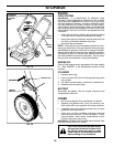
OPERATION
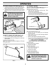
WHEEL
ADJUSTER
LEVER
FIG. 6
LEVER BACKWARD
TO LOWER MOWER
LEVER FORWARD
TO RAISE MOWER
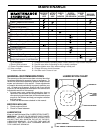
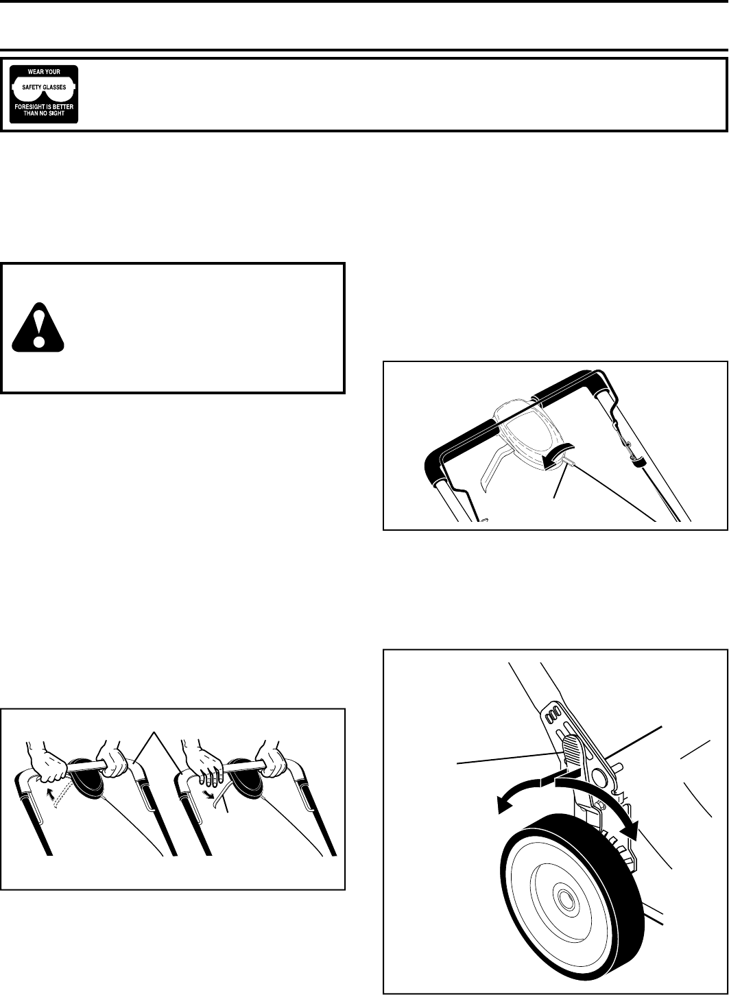
TO ADJUST CUTTING HEIGHT (See Fig. 6)
All four wheels are adjusted by a single lever.
• Pull adjuster lever toward wheel. To raise mower, move
lever forward to desired position. To lower mow er, move
the lever toward the rear.
FIG. 5B
ADJUSTMENT
TURNBUCKLE
TO ENGAGE
DRIVE CONTROL
DRIVE
CONTROL
LEVER
DRIVE CONTROL
DISENGAGED
OPERATOR PRESENCE CONTROL BAR
FIG. 5A