


17
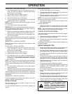
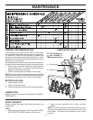
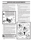
SERVICE AND ADJUSTMENTS
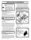
TO REPLACE BELTS
The auger and traction drive belts are not adjustable. If the
belts are damaged or begin to slip from wear, they should
be replaced. It is recommended that the belt(s) be replaced
by a qualified service center.
NOTE: It is recommended that both the auger and traction
drive belt be replaced at the same time.
The V-belts on your snow thrower are of special construc-
tion and should be replaced by original equipment manu-
facturer (OEM) belts available from your nearest dealer.
Using other than OEM belts can cause personal injury or
damage to the snow thrower.
WARNING: Belt replacement requires
separation of the snow thrower. While
separating the auger housing from the
frame assembly, it is important that an
assistant stand in the operating posi-
tion and hold the snow thrower handles.
Serious personal injury and/or damage
to the unit could occur if the snow
thrower should fall during the belt
changing process.
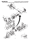
HINT: Insert a 3/8" drive ratchet (in the “ON” position) into
the square hole in idler arm and rotate ratchet clockwise to
relieve tension.
8. With tension relieved on idler, install new traction drive
belt around pulleys and inside belt keepers.
9. Place auger belt around and inside the groove of auger
pulley only.
10. While your assistant slowly raises handles to rejoin the
auger housing and frame assembly, pull up on the
auger belt and squeeze sides together above pulley so
belt is fully seated in groove of pulley.
11. Bring snow thrower completely together and check
carefully for proper routing of belts. If auger belt has
become dislodged from the pulley (by catching the idler
arm bracket while bringing snow thrower together),
separate the snow thrower and repeat step 10. Belt
must be fully seated in pulley groove when bringing the
snow thrower together.
12. Install the two (2) hex bolts and lock washers and
tighten securely.
13. INSTALL ENGINE PULLEY - Place belt in pulley groove
and slide pulley on crankshaft. Install flat washer,
lockwasher and bolt and tighten securely (30-35 ft. lbs.
torque). Make sure belt is inside belt keeper.
14. INSTALL BELT COVER and two (2) screws. Tighten
securely.
15. INSTALL DISCHARGE CHUTE – See “INSTALL DIS-
CHARGE CHUTE / CHUTE ROTATER HEAD” in the
Assembly section of this manual.
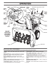
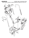
BELT KEEPER
IDLER ARM
SQUARE
HOLE
BOLT
LOCK
WASHER
TRACTION DRIVE BELT
CLUTCHING
IDLER ARM
BRACKET
AUGER
BELT
FLAT WASHER
AUGER PULLEY
AUGER
HOUSING
FRAME
ENGINE
PULLEY
LOCKWASHER
BOLT
1. REMOVE GASOLINE FROM FUEL TANK - Drain
gasoline from fuel tank into a suitable container, out-
doors, away from fire or flame. Wipe up any spilled
gasoline.
2. REMOVE DISCHARGE CHUTE - Loosen locknut se-
curing chute rotator head to mounting bracket only
enough to allow chute rotator head to be raised and
discharge chute to be removed from snow thrower.
3. REMOVE BELT COVER - See “TO REMOVE BELT
COVER” in this section of this manual.
4. REMOVE ENGINE PULLEY - Remove bolt, lockwasher
and flat washer securing pulley to engine crankshaft.
Remove outside (auger) pulley only from crankshaft.
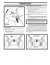
5. SEPARATE SNOW THROWER - With your assistant
standing in the operating position holding the handles,
remove the two (2) bolts and lock washers holding
auger housing and frame together.
WARNING: As the last bolt is removed,
have your assistant carefully lower the
handles down to the ground.
6. REMOVE AUGER BELT from around pulley.
7. RELIEVE TENSION ON TRACTION DRIVE BELT
IDLER and remove traction drive belt from around
pulleys.
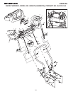
FRAME
ASSEMBLY
AUGER
HOUSING
HANDLES