7
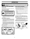
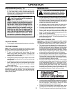
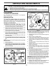
SIDE DIS CHARG ING (See Fig. 9)
• Mulcher plug must be installed into rear discharge
open ing of mower.
• Open mulcher door and install discharge defl ector
un der door as shown.
• Mower is now ready for discharging operation.
• To convert to mulching or bagging operation, dis charge
defl ector must be removed and mulcher door closed.
SIMPLE STEPS TO REMEMBER
WHEN CONVERTING YOUR LAWN MOWER
FOR MULCHING -
1. Rear mulcher plug installed.
2. Mulcher door closed.
FOR REAR BAGGING -
1. Rear mulcher plug removed.
2. Grass catcher installed.
3. Mulcher door closed.
FOR SIDE DISCHARGING -
1. Rear mulcher plug installed.
2. Discharge defl ector installed.
CAUTION: Do not run your lawn mower
without mulcher plug or ap proved grass
catch er in place. Nev er at tempt to op-
er ate the lawn mow er with the rear door
re moved or propped open.
OPERATION
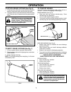
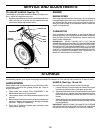
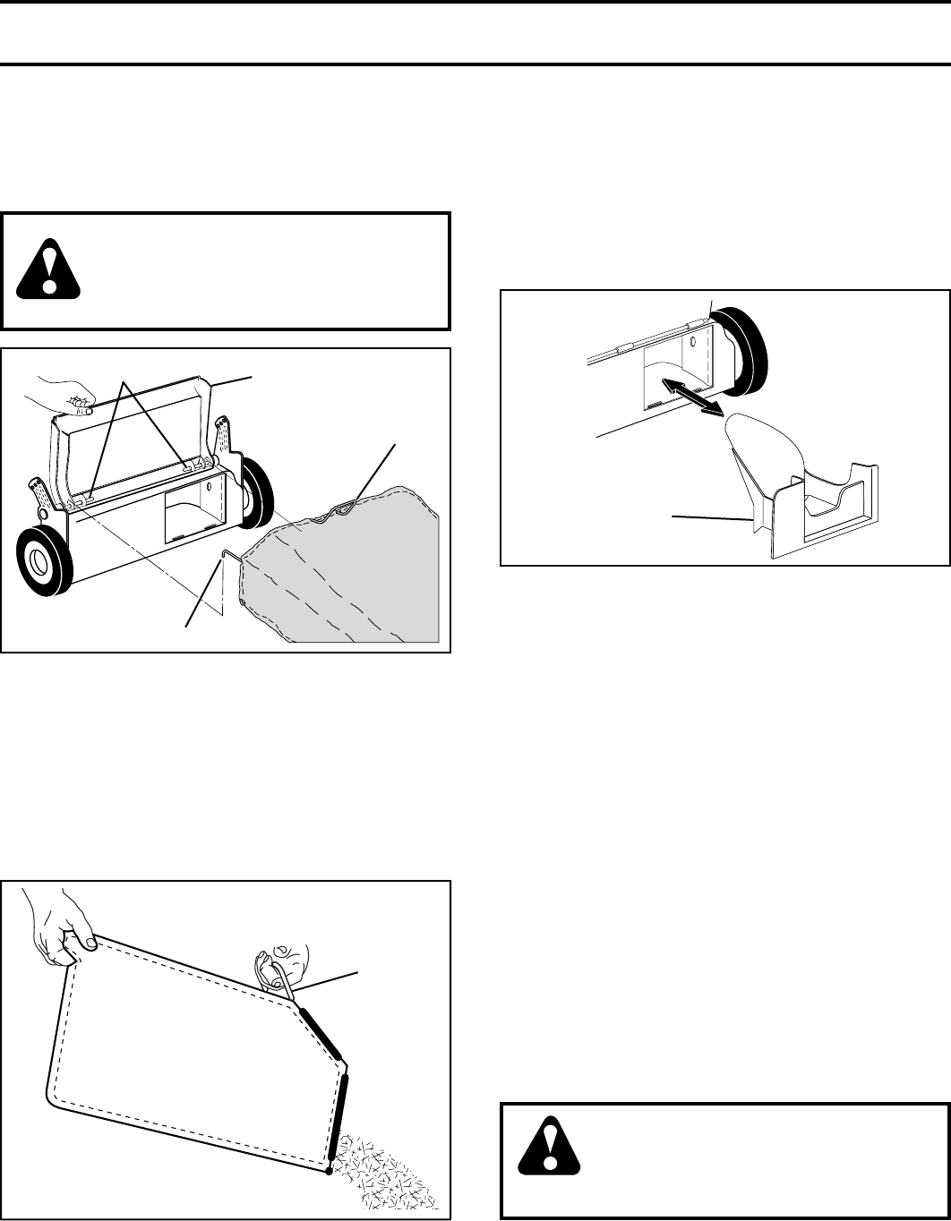
TO EMPTY GRASS CATCHER (See Fig. 7)
1. Lift up on grass catcher using the frame han dle.
2. Remove grass catcher with clippings from under lawn
mower han dle.
3. Empty clippings from bag.
NOTE: Do not drag the bag when emptying; it will cause
unnecessary wear.
TO CONVERT MOWER
Your lawn mower was shipped ready to be used as a
mulcher. To convert to bagging or discharging:
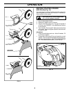
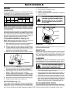
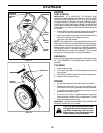
REAR BAGGING (See Fig. 8)
• Open rear door and remove mulcher plug. Store
mulcher plug in a safe place.
• You can now install the grass catcher.
• To convert to mulching or discharging operation, install
mulcher plug into rear discharge opening of mower.
FIG. 8
MULCHER PLUG
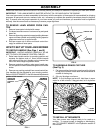
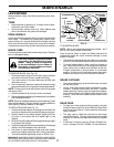
TO ATTACH GRASS CATCHER (See Fig. 6)
1. Lift the rear door of the lawn mower and place the grass
catcher frame side hooks onto the door pivot pins.
2. The grass catcher is secured to the lawn mower hous ing
when the rear door is lowered onto the grass catcher
frame.
CAUTION: Do not run your lawn mower
without mulcher plug or ap proved grass
catch er in place. Nev er at tempt to op-
er ate the lawn mower with the rear door
re moved or propped open.
FIG. 6
PIVOT PINS
REAR DOOR
GRASS
CATCHER
HANDLE
CATCHER FRAME HOOK
FIG. 7
FRAME
HANDLE


