


6
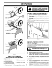
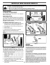
SIDE DISCHARGING (See Fig. 6)
• Rear door must be closed.
• Open mulcher door and install dis charge defl ector
under door as shown.
• Mower is now ready for discharging operation.
• To convert to mulching or bagging operation, dis charge
defl ector must be removed and mulcher door must be
closed.
TO CONVERT MOWER
Your lawn mower was shipped ready to be used as a
mulcher. To convert to bagging or discharging:
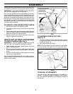
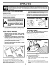
REAR BAGGING (See Fig. 5)
• Lift rear door of the lawn mower and place the grass
catcher frame hooks onto the door pivot pins.
• To convert to mulching or dis charg ing operation, remove
grass catch er and close rear door.
FIG. 5
PIVOT PINS REAR
DOOR
GRASS
CATCHER
HANDLE
CATCH ER FRAME HOOK
HOW TO USE YOUR LAWN MOWER
ENGINE SPEED
The engine speed was set at the factory for optimum per-
formance. Speed is not adjustable.
ENGINE ZONE CONTROL
CAUTION: Federal regulations require
an engine control to be installed on this
lawn mower in order to minimize the risk
of blade contact injury. Do not un der
any cir cum stanc es attempt to defeat
the function of the operator control.
The blade turns when the engine is
running.
• Your lawn mower is equipped with an operator presence
control bar which requires the operator to be positioned
behind the lawn mower handle to start and operate the
lawn mower.
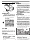
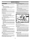
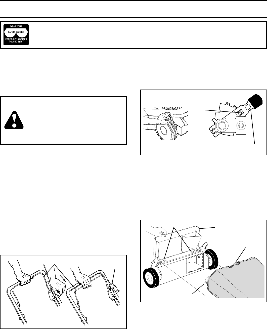
DRIVE CONTROL (See Fig. 3)
• Self-propelling is controlled by hold ing the operator
presence control bar down to the handle and push-
ing the drive control lever forward until it clicks; then
releasing the lever.
• Forward motion will stop when the operator presence
control bar is re leased. To stop forward motion without
stop ping engine, re lease the operator presence con-
trol bar slight ly until the drive control dis en gag es. Hold
op er a tor presence control bar down against handle to
con tin ue mowing without self-pro pel ling.
• To keep drive control engaged when turning corners,
push down on han dle and lift front wheels off ground
while turning lawn mower.
The operation of any lawn mower can result in foreign objects thrown into the eyes, which can result in
severe eye damage. Always wear safety glasses or eye shields while operating your lawn mower or per-
forming any adjustments or repairs. We recommend standard safety glasses or a wide vision safety mask
over spectacles.
OPERATION
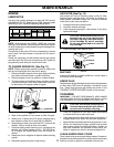
FIG. 4
LEVER BACKWARD TO LOWER MOWER
LEVER FORWARD TO RAISE MOWER
PLATE
TAB
LEVER
TO ENGAGE
DRIVE CONTROL
DRIVE
CONTROL
DRIVE
CONTROL
DISENGAGED
OPERATOR PRESENCE CONTROL BAR
FIG. 3
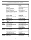
TO ADJUST CUTTING HEIGHT (See Fig. 4)
Raise wheels for low cut and lower wheels for high cut,
adjust cutting height to suit your requirements. Me di um
position is best for most lawns.
• To change cutting height, squeeze adjuster lever to ward
wheel. Move wheel up or down to suit your re quire ments.
Be sure all wheels are in the same setting.
NOTE: Adjuster is properly positioned when plate tab inserts
into hole in lever. Also, 9-position adjusters (if so equipped)
allow lever to be positioned between the plate tabs.