


14
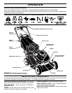
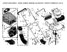
LAWN MOWER
TO ADJUST CUTTING HEIGHT
See “TO ADJUST CUTTING HEIGHT” in the Operation
section of this manual.
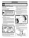
REAR DEFLECTOR
The rear defl ector, attached between the rear wheels of
your mower, is provided to minimize the possibility that
objects will be thrown out of the rear of the mower into
the operator's mowing position. If the defl ector becomes
damaged, it should be replaced.
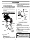
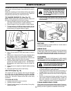
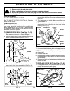
TO REMOVE DRIVE BELT (See Figs. 17–19)
1. Disconnect spark plug wire from spark plug and place
wire where it cannot come in contact with plug.
2. Remove screws retaining drive cover and remove drive
cover from lawn mower housing (See Fig. 17).
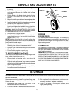
SERVICE AND ADJUSTMENTS
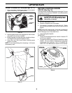
7. Use a wood block between blade and mower hous ing
to prevent blade from turning when re mov ing blade bolt.
NOTE: Protect your hands with gloves and/or wrap blade
with heavy cloth.
8. Remove blade bolt.
9. Remove blade, attaching hardware (bolt, lock wash er,
hardened wash er), blade adapter and debris shield as
one assembly.
10. Remove drive belt from blade adapter and debris shield;
discard old belt.
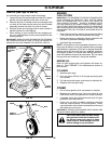
TO REPLACE DRIVE BELT (See Figs. 17–20)
1. Place new drive belt in the belt retainer of the debris
shield. Be sure to route belt between belt keepers and
through slot as shown (See Fig. 20).
TRAILING
EDGE
CRANKSHAFT
DEBRIS
SHIELD
SCREW
BLADE
ADAPTER
HARDENED
WASHER
LOCK-
WASHER
BLADE
BOLT
TAB
HOUSING
HOLE
FIG. 19
SCREWS
DRIVE
COVER
LAWN
MOWER
HOUSING
FIG. 17
3. Remove drive cable from anchor, then detach it and
return spring from idler arm assembly (See Fig. 18).
CAUTION: TO AVOID SERIOUS INJURY, BEFORE PERFORMING ANY SERVICE OR ADJUSTMENTS:
1. Release control bar and stop engine.
2. Make sure the blade and all moving parts have completely stopped.
3. Disconnect spark plug wire from spark plug and place wire where it cannot come in contact
with plug.
4. Pivot idler arm assembly to slacken drive belt, then
remove drive belt from drive pulley, belt keepers and
idler arm.
5. Turn lawn mower on its side. Make sure air fi lter and
carburetor are up.
6. Remove screw securing debris shield. Note that the
debris shield has a tab which fi ts into a gap in the
housing (See Fig. 19).
DEBRIS SHIELD
BELT
RETAINER
BELT
KEEPERS
DRIVE
BELT
SLOT
TAB
FIG. 20
DRIVE CABLE ANCHOR
IDLER ARM
ASSEMBLY
BELT
KEEPER
DRIVE
PULLEY
HOUSING
HOLE
PIVOT
DRIVE BELT
FIG. 18
RETURN SPRING