


7
3. Operate mower to see if drive speed has increased. If
there is no increase, the drive belt is worn and needs
to be re placed.
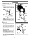
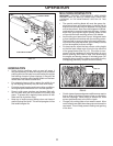
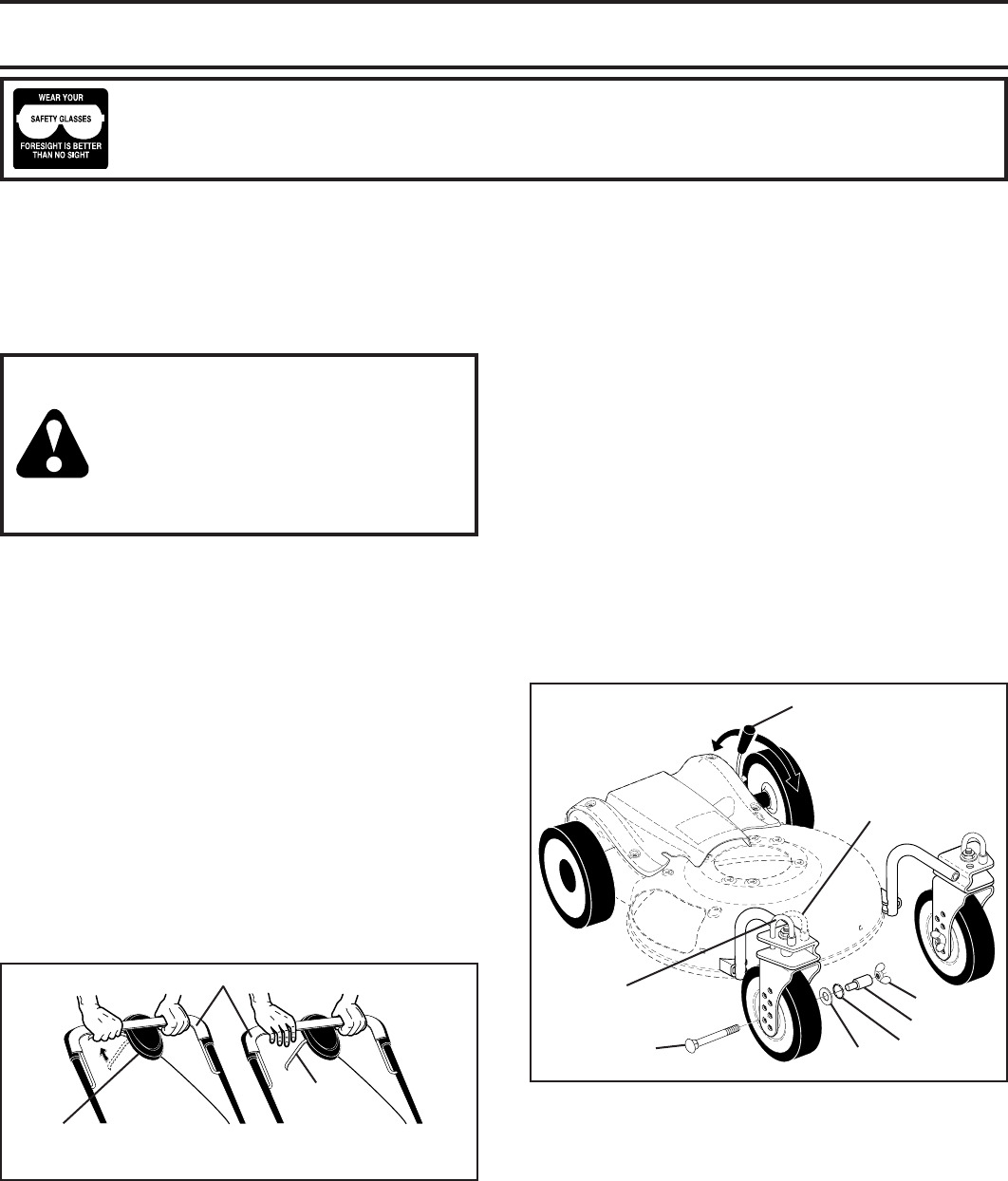
TO ADJUST CUTTING HEIGHT (See Fig. 6)
Both rear wheels are adjusted by a single lever on the left
rear wheel.
• Pull adjuster lever toward wheel. To raise mower, move
lever forward to desired position. To lower mow er, move
the lever toward the rear.
NOTE: There are seven (7) height adjustment positions
for the rear wheels.
Both front wheels are adjusted as follows:
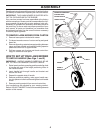
1. Remove wheel, bolt, and hardware and reassemble in
desired ad just ment hole.
2. Reinstall wheel components in the same order as they
were before removal. Tighten securely.
NOTE: There are seven (7) height adjustment holes for the
front wheels. Be sure both front wheels are in the same hole.
IMPORTANT: BE SURE TO ADJUST BOTH FRONT AND REAR
WHEELS TO THE SAME HEIGHT.
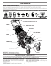
HOW TO USE YOUR LAWN MOWER
ENGINE SPEED
The engine speed was set at the factory for optimum per-
formance. Speed is not adjustable.
ENGINE ZONE CONTROL
CAUTION: Federal regulations require
an engine control to be installed on this
lawn mower in order to minimize the risk
of blade contact injury. Do not un der
any cir cum stanc es attempt to defeat
the function of the operator control.
The blade turns when the engine is
running.
• Your lawn mower is equipped with an operator presence
control bar which requires the operator to be positioned
behind the lawn mower handle to start and operate the
lawn mower.
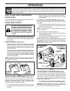
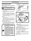
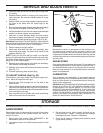
DRIVE CONTROL (See Fig. 5)
• Self-propelling is controlled by hold ing the operator
presence control bar down to the handle and pulling
the drive control lever rearward to the handle. The
farther toward the handle the lever is pulled, the faster
the unit will travel.
• Forward motion will stop when either the operator pres-
ence control bar or drive control lever are released. To
stop forward motion without stop ping engine, re lease
the drive control lever only. Hold op er a tor presence
control bar down against handle to con tin ue mowing
without self-propelling.
NOTE: If after releasing the drive control the mower will
not roll backwards, push the mower forward slightly to
disengage drive wheels.
The operation of any lawn mower can result in foreign objects thrown into the eyes, which can result
in severe eye damage. Always wear safety glasses or eye shields while operating your lawn mower or
performing any adjustments or repairs. We recommend standard safety glasses or a wide vision safety
mask over spectacles.
OPERATION
FIG. 5
TO ENGAGE
DRIVE
CONTROL
DRIVE
CONTROL
LEVER
DRIVE
CONTROL
DISENGAGED
OPERATOR PRESENCE CONTROL BAR
ADJUSTMENT
BUTTON (ON
UNDERSIDE)
DRIVE CONTROL ADJUSTMENT (See Fig. 5)
Over time, the drive control system may become “loose”,
resulting in decreased speed. There is a button on the
un der side of the drive control housing to increase tension
on the drive cable. Pro ceed as follows:
1. Turn unit off and disconnect spark plug wire from plug.
2. Pull out button on underside of drive control, then push
it back in.
CASTER WHEEL OPERATION (See Fig. 6)
The front wheels can be “locked” into position or set to
“freewheel” for better maneuverability. Placing the lockbars
in the outer holes of the adjustment brackets “locks” the
front wheels. Likewise, placing the lockbars in the inner
holes of the adjustment brackets allows the front wheels
to spin freely (“freewheel”).
• Lift lockbar until the frontmost end clears the adjust-
ment bracket, then pivot lockbar to desired position.
IMPORTANT: FRONT WHEELS MUST BE “LOCKED” INTO
POSITION WHEN OPERATING ON A SLOPE. MOW ACROSS
THE FACE OF SLOPES: NEVER UP AND DOWN.
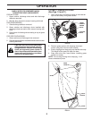
FIG. 6
LEVER BACKWARD
TO LOWER REAR
OF MOWER
LEVER FORWARD
TO RAISE REAR
OF MOWER
HEIGHT ADJUSTER LEVER
BOLT
SPACER
“FREEWHEEL”
POSITION
LOCKBAR
(“LOCKED” POSITION)
WING NUT
WASHER
O-RING