


12
LAWN MOWER
TO ADJUST CUTTING HEIGHT
See “TO ADJUST CUTTING HEIGHT” in the Operation
section of this manual.
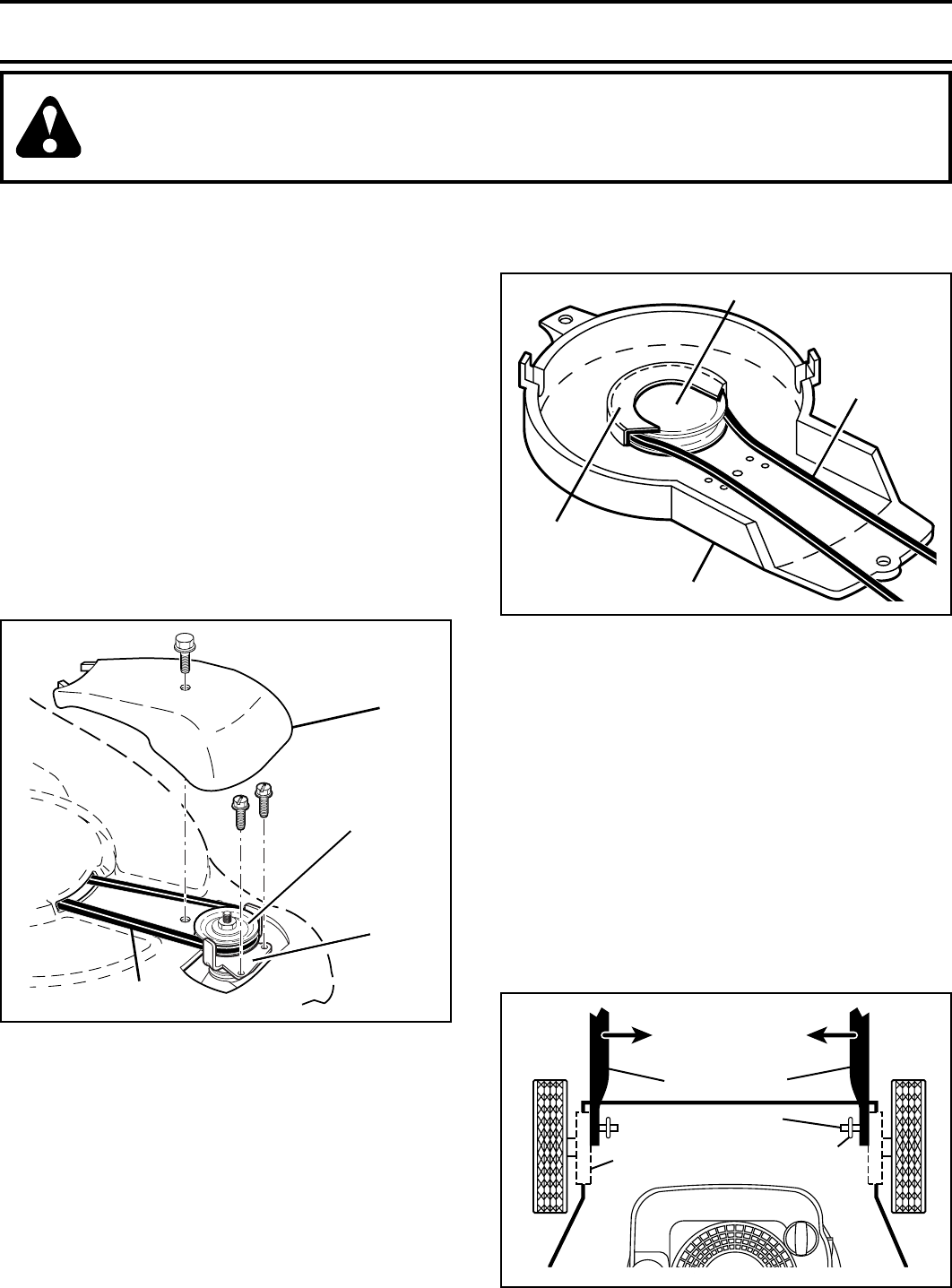
REAR DEFLECTOR
The rear defl ector, attached between the rear wheels of
your mower, is provided to minimize the possibility that
objects will be thrown out of the rear of the mower into
the operator's mowing position. If the defl ector becomes
damaged, it should be replaced.
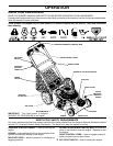
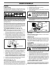
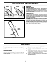
TO REMOVE DRIVE BELT (See Fig. 14)
1. Remove drive cover and belt keeper.
2. Remove belt from gearcase pulley.
3. Turn lawn mower on its side with air fi lter and car bu -
re tor down.
4. Remove blade, engine pulley and debris shield.
5. Remove engine pulley and belt from debris shield.
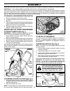
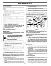
CAUTION: TO AVOID SERIOUS INJURY, BEFORE PERFORMING ANY SERVICE OR ADJUSTMENTS:
1. Release control bar and stop engine.
2. Make sure the blade and all moving parts have completely stopped.
3. Disconnect spark plug wire from spark plug and place where it cannot come in contact with plug.
SERVICE AND ADJUSTMENTS
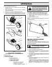
FIG. 16
LOWER HANDLE
HANDLE
BRACKET
HAIRPIN
COTTER
SQUEEZE
TO ADJUST
MOUNTING PIN
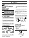
TO REPLACE DRIVE BELT (See Fig. 15)
1. Place new drive belt in engine pulley and belt retainer
of debris shield.
2. Route the other end of the new drive belt through hole
in housing.
3. Reinstall debris shield.
4. Return mower to upright po si tion.
5. Install new belt on gearcase pulley.
6. Reinstall belt keeper and drive cover.
NOTE: Always use factory approved belt to assure proper
fi t and long life.
7. Turn lawn mower on its side with air fi lter and car bu -
re tor down.
8. Reinstall blade.
BELT
KEEPER
DRIVE
COVER
FIG. 14
GEARCASE
PULLEY
BELT
DEBRIS SHIELD
BELT
BELT RETAINER
FIG. 15
ENGINE PULLEY
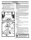
TO ADJUST HANDLE (See Figs. 16 thru 18)
The handle can be mounted in a high or low position. The
mounting holes in the bottom of lower handle are off center
for raising or lowering the handle.
1. Remove upper handle and all wire tie(s) securing
cable(s) to lower handle.
2. Remove hairpin cotters from lower handle bracket
mount ing pin.
3. Squeeze lower handle in to remove from mounting pins.
4. Turn lower handle over to raise or lower handle.
5. Squeeze lower handle in and po si tion holes onto
mount ing pins on handle bracket.
6. Reassemble upper handle and all parts removed from
lower handle.