


14
CUSTOMER RESPONSIBILITIES
MUFFLER
Do not operate tiller without muffler. Do not tamper with
exhaust system. Damaged mufflers or spark arresters
could create a fire hazard. Inspect periodically and replace
if necessary. If your engine is equipped with a spark
arrester screen assembly, remove every 50 hours for
cleaning and inspection. Replace if damaged.
SPARK PLUG
Replace spark plugs at the beginning of each tilling season
or after every 50 hours of use, whichever comes first. Spark
plug type and gap setting is shown in “PRODUCT SPECI-
FICATIONS” on page 3 of this manual.
TRANSMISSION
Your transmission is sealed and will only require lubrication
if serviced.
CLEANING
• Clean engine, wheels, finish, etc. of all foreign matter.
• Keep finished surfaces and wheels free of all gasoline,
oil, etc.
• Protect painted surfaces with automotive type wax.
We do not recommend using a garden hose to clean your
unit unless the muffler, air filter and carburetor are covered
to keep water out. Water in engine can result in a shortened
engine life.
SERVICE AND ADJUSTMENTS
CAUTION: Disconnect spark plug wire from spark plug and place wire where it cannot come into
contact with plug.
TILLER
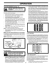
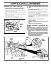
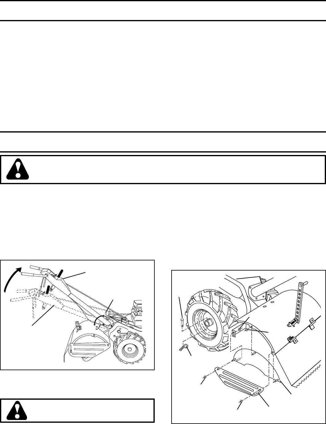
TO ADJUST HANDLE HEIGHT (See Fig. 20)
Select handle height best suited for your tilling conditions.
Handle height will be different when tiller digs into soil.
• First loosen handle lock lever.
• Handle can be positioned at different settings between
“HIGH” and “LOW” positions.
• Retighten handle lock lever securely after adjusting.
FIG. 20
HANDLE
(LOW POSITION)
TIRE CARE
CAUTION: When mounting tires, un-
less beads are seated, overinflation
can cause an explosion.
• Maintain 20 PSI (1.4 kg/cm
2
) of tire pressure. If tire
pressures are not equal, tiller will pull to one side.
• Keep tires free of gasoline or oil which can damage
rubber.
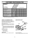
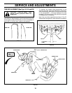
TO REMOVE WHEEL (See Fig. 21)
• Place blocks under transmission to keep tiller from
tipping.
• Remove outer side shield by removing nuts “A” and “B”.
• Remove inner side shield by removing nuts “C” and
“D”.
• Remove hairpin clip and clevis pin from wheel.
• Remove wheel and tire.
• Repair tire and reassemble.
CLEVIS
PIN
INNER SIDE
SHIELD
OUTER
SIDE
SHIELD
NUT
“D”
HAIRPIN
CLIP
NUT “C”
NUT “A”
NUT “B”
FIG. 21
HANDLE
LOCK
LEVER
HANDLE
(HIGH POSITION)