11
MAINTENANCE
LAWN MOWER
Always observe safety rules when performing any main-
te nance.
TIRES
• Keep tires free of gasoline, oil, or insect control chem-
i cals which can harm rubber.
• Avoid stumps, stones, deep ruts, sharp objects and
other hazards that may cause tire damage.
DRIVE WHEELS
Check front drive wheels each time be fore you mow to be
sure they move freely.
The wheels not turning freely means trash, grass cuttings,
etc. are in the drive wheel area and must be cleaned to
free drive wheels.
If necessary to clean the drive wheels, be sure to clean
both front wheels.
1. Remove hubcaps, locknuts and washers.
2. Remove wheels from wheel ad just ers.
3. Remove any trash or grass cuttings from inside the
dust cover, pinion and/or drive wheel gear teeth.
4. Put wheels back in place.
NOTE: If after cleaning, the drive wheels do not turn freely,
contact a qualifi ed service center.
BLADE CARE
For best results, mower blade must be kept sharp. Re place
bent or dam aged blades.
CAUTION: Use only a replacement blade
approved by the manufacturer of your
mower. Using a blade not approved
by the manufacturer of your mower is
hazardous, could damage your mower
and void your warranty.
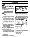
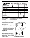
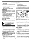
TO REMOVE BLADE (See Fig. 11)
1. Disconnect spark plug wire from spark plug and place
wire where it cannot come in contact with plug.
2. Turn lawn mower on its side. Make sure air fi lter and
carburetor are up.
3. Use a wood block between blade and mower hous ing
to prevent blade from turning when re mov ing blade bolt.
NOTE: Protect your hands with gloves and/or wrap blade
with heavy cloth.
4. Remove blade bolt by turning counter-clockwise.
5. Remove blade and attaching hardware (bolt, lock wash er
and hardened wash er).
NOTE: Remove the blade adapter and check the key inside
hub of blade adapter. The key must be in good condition to
work properly. Replace adapter if dam aged.
TO REPLACE BLADE (See Fig. 11)
1. Position the blade adapter on the engine crank shaft. Be
sure key in adapter and crankshaft key way are aligned.
2. Position blade on the blade adapter aligning the two
(2) holes in the blade with the raised lugs on the
adapter.
3. Be sure the trailing edge of blade (opposite sharp edge)
is up toward the engine.
4. Install the blade bolt with the lock washer and hard ened
washer into blade adapter and crank shaft.
5. Use block of wood between blade and lawn mower
housing and tighten the blade bolt, turning clock wise.
• The recommended tightening torque is 35-40 ft. lbs.
IMPORTANT: BLADE BOLT IS HEAT TREATED. IF BOLT NEEDS
REPLACING, REPLACE ONLY WITH APPROVED BOLT SHOWN
IN THE REPAIR PARTS SECTION OF THIS MANUAL.
TO SHARPEN BLADE
NOTE: We do not recommend sharp en ing blade - but if
you do, be sure the blade is balanced.
Care should be taken to keep the blade balanced. An
un bal anced blade will cause eventual damage to lawn
mower or engine.
• The blade can be sharp ened with a fi le or on a grinding
wheel. Do not attempt to sharpen while on the mower.
• To check blade balance, drive a nail into a beam or
wall. Leave about one inch of the straight nail ex posed.
Place center hole of blade over the head of the nail.
If blade is balanced, it should remain in a horizontal
position. If either end of the blade moves downward,
sharpen the heavy end until the blade is balanced.
GRASS CATCHER
• The grass catcher may be hosed with water, but must
be dry when used.
• Check your grass catcher often for damage or de te -
ri o ra tion. Through normal use it will wear. If catcher
needs replacing, replace only with ap proved replace-
ment catcher shown in the Repair Parts section of this
manual. Give the lawn mower model number when
ordering.
GEAR CASE
• To keep your drive system working properly, the gear
case and area around the drive should be kept clean
and free of trash build-up. Clean under the drive cover
twice a season.
• The gear case is fi lled with lubricant to the proper level
at the factory. The only time the lubricant needs atten-
tion is if service has been performed on the gear case.
• If lubricant is required, use only ELF Multis EP00.
Do not substitute.
FIG. 11
BLADE
BOLT
HARDENED
WASHER
LOCK
WASHER
BLADE ADAPTER KEY
BLADE
TRAILING EDGE
CRANKSHAFT
KEY WAY
CRANKSHAFT


