


English – 13
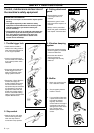
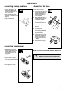
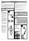
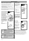
Assembling the blade
Fit the blade as follows:
1. Fit the drive disc (A) on the
outgoing shaft. Make sure
that the edge that fits in
the hole of the blade is
facing outward.
2. Block the blade rotation by
inserting locking pin in the
hole behind the blade
guard engaging it in the
corresponding hole in the
drive disc.
3. Fit the blade (B) on the
drive disc.
4. Fit the support
flange (C). The support
flange must be fitted with
its outer edge hard up
against the blade.
5. Fit the locknut (D). NOTE!
The locknut has left-hand
threads. The tightening
torque of the locknut is 35
– 50 Nm.
6. Remove the locking pin.
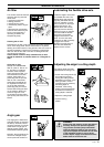
ASSEMBLY
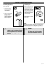
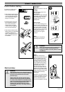
Assembling the loop handlebar
• Position the handle on the
shaft. Note that the handle
must be mounted below the
arrow on the shaft.
• Fit the bolt, securing plate
and wing nut as shown in the
diagram.
• Tighten the wing nut.
A
C
B
D
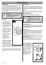
NOTE! Do not forget to remove the locking pin before using
the machine.
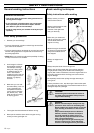
WARNING!
Under no circumstances may the edge cutter
blade be used without the blade guard fitted.
!
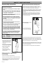
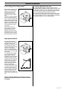
Assembling the angle gear
• Assemble the angle gear
back on the supporting tube.
Turn the blade so that the
drive shaft engages in the
angle gear.
• Position the angle gear so
that its slot is aligned with the
line on the supporting tube.
• Firmly tighten the screw.