


32 - English
3. INSTALLATION
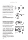
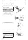
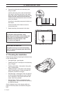
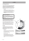
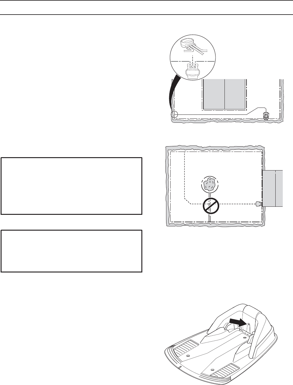
6. Connect the guide wire to the boundary wire
using a coupler:
Insert the boundary wire in each of the holes in
the coupler. Insert the guide wire in the centre
hole in the coupler. Check that the wires are fully
inserted into the coupler so that the ends are
visible through the transparent area on the other
side of the coupler.
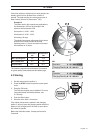
Use pliers to completely compress the button on
the coupler.
It does not matter which holes are used to
connect each wire.
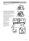
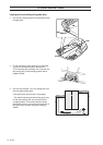
7. Staple down/bury the connector in the lawn.
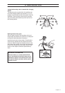
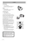
3.7 Checking the installation
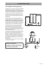
Check the loop signal by inspecting the indicator lamp
on the charging station.
• Solid green light = good signals.
• Flashing blue light = interruption in the boundary
loop, no signal.
• Flashing yellow light = interruption in the guide
loop, no guide signal.
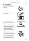
• Flashing red light = interruption in the charging
station's antenna plate. Contact the dealer for
assistance, see Memo on page 4.
• Solid blue light = weak signal. This may depend
on the boundary loop being too long or that the
wire is damaged. If the robotic lawnmower still
works, this is not a problem.
• Solid red light = fault in a circuit board in the
charging station. The fault should be rectified by
an authorized dealer.
See 9.2 Indicator lamp in the charging station on
page 64 if the lamp does not indicate a solid green
light.
IMPORTANT INFORMATION
The function of the guide wire varies
depending on the layout of the working area.
This is why it is recommended to test the
installation using this function . See
6.4 Installation on page 45.
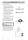
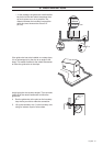
IMPORTANT INFORMATION
The guide wire may not cross the boundary
wire, for instance a boundary wire that is laid
out to an island.