


English – 25
ASSEMBLY
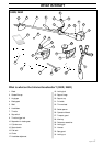
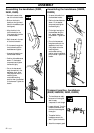
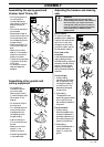
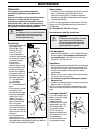
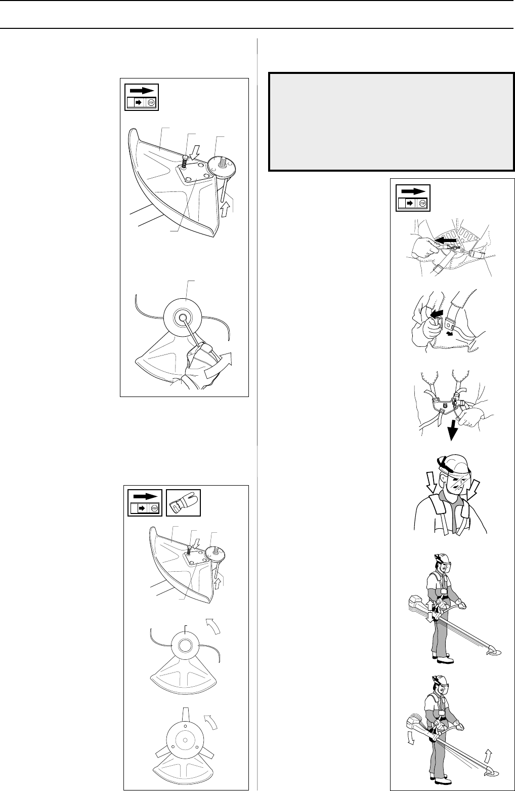
Assembling the spray guard and
trimmer head Trimmy SII
• Fit the correct guard (A)
for working with a
trimmer head. Secure
using 4 bolts (L) and the
support plate (M) as
shown.
• Fit the driver plate (B) on
the drive shaft.
• Rotate the drive shaft so
that one of the holes in the
driver plate lines up with
the corresponding hole in
the gear housing.
• Insert the locking pin (C)
into the hole to lock the
shaft.
• Screw on the trimmer
head (H) in the opposite
direction to the normal
direction of rotation.
• Tighten the trimmer head
to a torque of 35-50 Nm
(3,5-5 kpm).
• To remove the trimmer
head just reverse the
sequence.
B
A
L
M
C
H
B
A
L
M
C
H
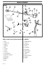
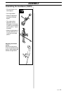
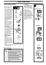
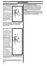
Adjusting the harness and clearing
saw
Quick release
On the front is an easily
accessible, quick release catch.
Use this if the engine should
catch fire or in any other
emergency situation when
you quickly need to take off
the harness and machine.
Even load on the
shoulders
A well-adjusted harness and
clearing saw significantly
facilitates working. Adjust the
harness for the best working
position. Tension the side
straps so that the weight is
evenly distributed across the
shoulders.
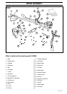
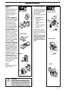
Correct height
1 Forestry clearing
Adjust the carrier strap so
that the suspension hook
comes approximately 10
cm under the hip. The
blade should be angled
forward a little.
2 Grass clearing
The suspension hook
should hang approximately
20 cm under the hip so
that the blade is parallel to
the ground.
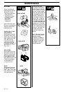
Correct balance
1 Forestry clearing
Move the suspension eye
forwards or backwards. If
the blade is balanced a 10-
20 cm above the ground it
is easier to avoid stones.
2 Grass clearing
Let the blade balance at a
comfortable clearing
height, i.e. close to the
ground.
!
WARNING!
When working with the clearing saw it
should always be hooked in the harness. If
this is not done, you cannot control the
clearing saw safely and this can result in
injury to yourself or someone else. Never
use a harness with a defective quick
release catch.
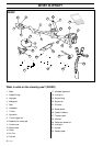
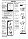
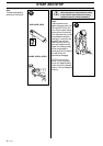
• Fit the guard (A)
intended for use with
the trimmer head.
Secure using four bolts
(L) and the support plate
(M) as shown in the
diagram.
• Fit the disc drive (B) on
the output axle.
• Turn the blade axle until
one of the disc drive’s
holes aligns with the
corresponding hole in
the gear housing.
• Insert the locking pin
(C) into the hole to lock
the axle.
• Screw on the trimmer
head (H) in the
direction of rotation.
• Dismantling takes place
in the reverse order.
Assembling other guards and
cutting equipment