


9
ASSEMBLY
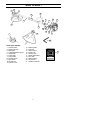
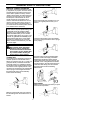
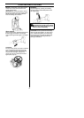
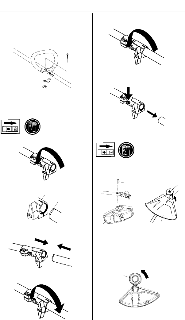
Fitting the trimmer guard and
trimmer head
S Fit t he correct trimmer guard (D) for use
with the trimmer head. Hook the trimmer
guard/combination guard onto the fitting
on the shaft and secure with the bolt (E).
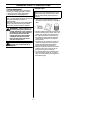
Assembling and dismantling
the two--piece shaft
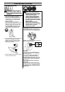
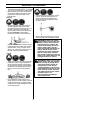
Assembly:
S Loosen the coupling by turning the knob.
S Align the tab of the attachment (A) with
the arrow o n the coupling (B).
S Push the attachment into the coupling until
the attachment snaps into place.
S Before using the unit, tighten the knob se-
curely.
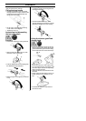
S Fit the drive disc (F) on the output shaft.
S Turn the shaft until one of the holes in the
drive disc aligns with the corresponding
hole in the gear housing.
S Insert hex wrench (G) in the hole to lock
the shaft.
S Screw on the trimmer head (H) in the op-
posite direction to the direction of rota-
tion.
N
O
TE: Make sure unit is assembled cor-
rectly as shown in this manual.
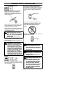
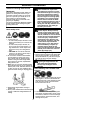
Fitting the l oop handle
S Position the handle on the upper shaft
leaning towards the engine. Note that the
handle must be m ounted between the
two arrows on the shaft.
S Fit the screw, securing plate and wing
nut as shown in the diagram.
S Tighten the wing nut.
D
E
D
F
G
H
S To dismantle, follow the instructions in
the reverse order.
B
A
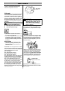
Dismantling:
S Loosen the coupling by turning the knob
(at least three times).
S Push and hold the button (C). While
securely holding the engine end, pull the
attachment straight out of the coupling.
C