


12 – English
ASSEMBLY
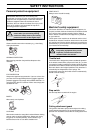
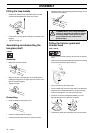
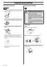
Fitting the loop handle
• Position the handle on the shaft. Note that the handle
must be mounted below the arrow on the shaft.
• Fit the screw, securing plate and wing nut as shown in the
diagram.
• Tighten the wing nut.
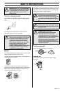
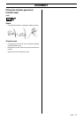
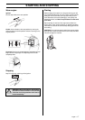
Assembling and dismantling the
two-piece shaft
(123LD)
Assembly:
• Make sure the knob is loose.
• Align the cut-out in the lower part of the shaft with the
coupling locking tab on the upper part of the shaft. Then
lock the sections together.
• Tighten the knob.
Dismantling:
• Undo the knob (at least three turns).
• Push the knob towards the coupling.
• Carefully twist the lower half of the shaft to unlock it.
• Hold both parts of the shaft and pull the lower part of the
shaft out of the coupling.
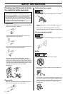
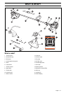
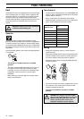
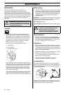
Fitting the trimmer guard and
trimmer head
(123L, 123LD)
• Fit the correct trimmer guard (A) for use with the trimmer
head.
Hook the trimmer guard/combination guard onto the fitting
on the shaft and secure with the bolt (L).
• Fit the drive disc on the output shaft.
• Turn the blade shaft until one of the holes in the drive disc
aligns with the corresponding hole in the gear housing.
• Insert the locking pin in the hole to lock the shaft.
• Screw on the trimmer head/plastic blades (H) in the
opposite direction to the direction of rotation.
• To dismantle, follow the instructions in the reverse order.
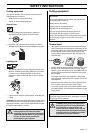
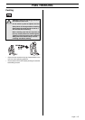
!
WARNING! Never use a cutting attachment
without an approved guard. See the chapter
on Technical data. If an incorrect or faulty
guard is fitted this can cause serious
personal injury.
A
H
H