


11
OPERATION
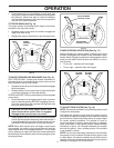
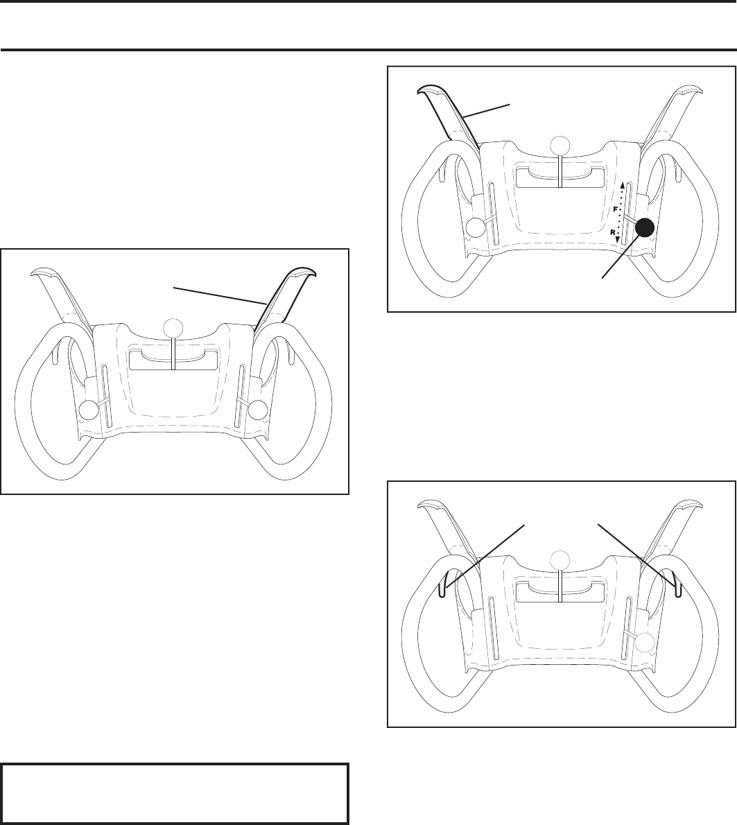
AUGER
CONTROL
LEVER
FIG. 15
DRIVE SPEED
CONTROL LEVER
TRACTION DRIVE
CONTROL LEVER
FIG. 16
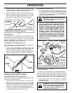
LH TURN
TRIGGER
RH TURN
TRIGGER
FIG. 17
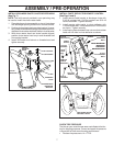
• Press downward on chute defl ector control lever and
move lever forward to lower the defl ector and decrease
the distance. Move lever back to raise the defl ector
and increase the distance. Be sure lever springs back
and locks into desired position.
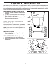
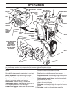
TO THROW SNOW (See Fig. 15)
The auger rotation is controlled by the auger control lever
located on the right side handle.
• Squeeze auger control lever to handle to engage the
auger and throw snow.
• Release the auger control lever to stop throwing snow.
TO MOVE FORWARD AND BACKWARD (See Fig. 16)
SELF-PROPELLING, forward and reverse movement of
the snow thrower, is controlled by the traction drive control
lever located on the left side handle.
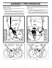
• Squeeze traction drive control lever to handle to en gage
the drive system.
• Release traction drive control lever to stop the forward
or reverse movement of the snow thrower.
SPEED and DIRECTION are controlled by the drive speed
control lever.
• Press downward on the speed control lever and move
lever to de sired po si tion BE FORE engaging the trac-
tion drive control lever. Be sure lever springs back and
locks into desired position.
CAUTION: Do not move speed con trol le ver
when traction drive control lever is en gaged.
Damage to the snow thrower can result.
• Slower speeds are for heavier snow and faster speeds
are for light snow and transporting the snow thrower. It
is recommended that you use a slower speed until you
are familiar with the operation of the snow thrower.
NOTE: When both traction drive and auger control levers
are engaged, the traction drive control lever will lock the
auger control lever in the engaged position. This will allow
you to release your right hand from the handle and adjust
the discharge chute direction without interrupting the snow
throwing process.
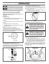
POWER STEERING OPERATION (See Fig. 17)
Steering triggers are used to assist in steering your snow
thrower. The triggers are located on the underside of each
handle. When a trigger is squeezed, it disengages the drive
wheel on that side of snow thrower and allows it to turn in
that direction.
• To turn left – squeeze left side trigger.
• To turn right – squeeze right side trigger.
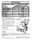
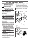
TO ADJUST SKID PLATES (See Fig. 18)
NOTE: The wrench provided in your parts bag may be used
to adjust the skid plates.
Skid plates are located on each side of the auger housing
and adjust the clearance between the scraper bar and the
ground surface. Adjust skid plates evenly to proper height
for current surface conditions. For removal of snow in
normal con di tions, such as a paved driveway or side walk,
place skid plates in the highest position (lowest scraper
clear ance) to give a 1/8" clearance between the scraper
bar and the ground. Use a middle position if the surface
to be cleared is uneven.
NOTE: It is not recommended to operate the snow thrower
over gravel or rocky surfaces. Objects such as gravel, rocks
or other debris, can easily be picked up and thrown by the
impeller, which can cause serious personal injury, property
dam age or damage to the snow thrower.