


7
Assembly
Your generator requires some assembly and is ready for use
after it has been properly serviced with the recommended
fuel and oil.
If you have any problems with the assembly of your generator,
please call the generator helpline at (877) 224-0458. If calling
for assistance, please have the model, revision, and serial
number from the data tag available. See Generator Controls
and Features for data tag location.
Unpack Generator
1. Set the carton on a rigid, flat surface.
2. Remove everything from carton except generator.
3. Open carton completely by cutting each corner from
top to bottom.
4. Leave generator on carton to install wheel kit.
The generator is supplied with:
• Engine oil bottle
• Operator’s manual
• Wheel kit
Install Wheel Kit
The wheel kit is designed to greatly improve the portability of
your generator.
NOTE: Wheel kit is not intended for over-the-road use.
You will need the following tools to install these
components:
• 13mm socket wrench
• 13mm open end wrench
• Pliers
• Safety glasses
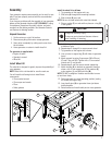
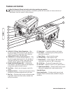
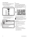
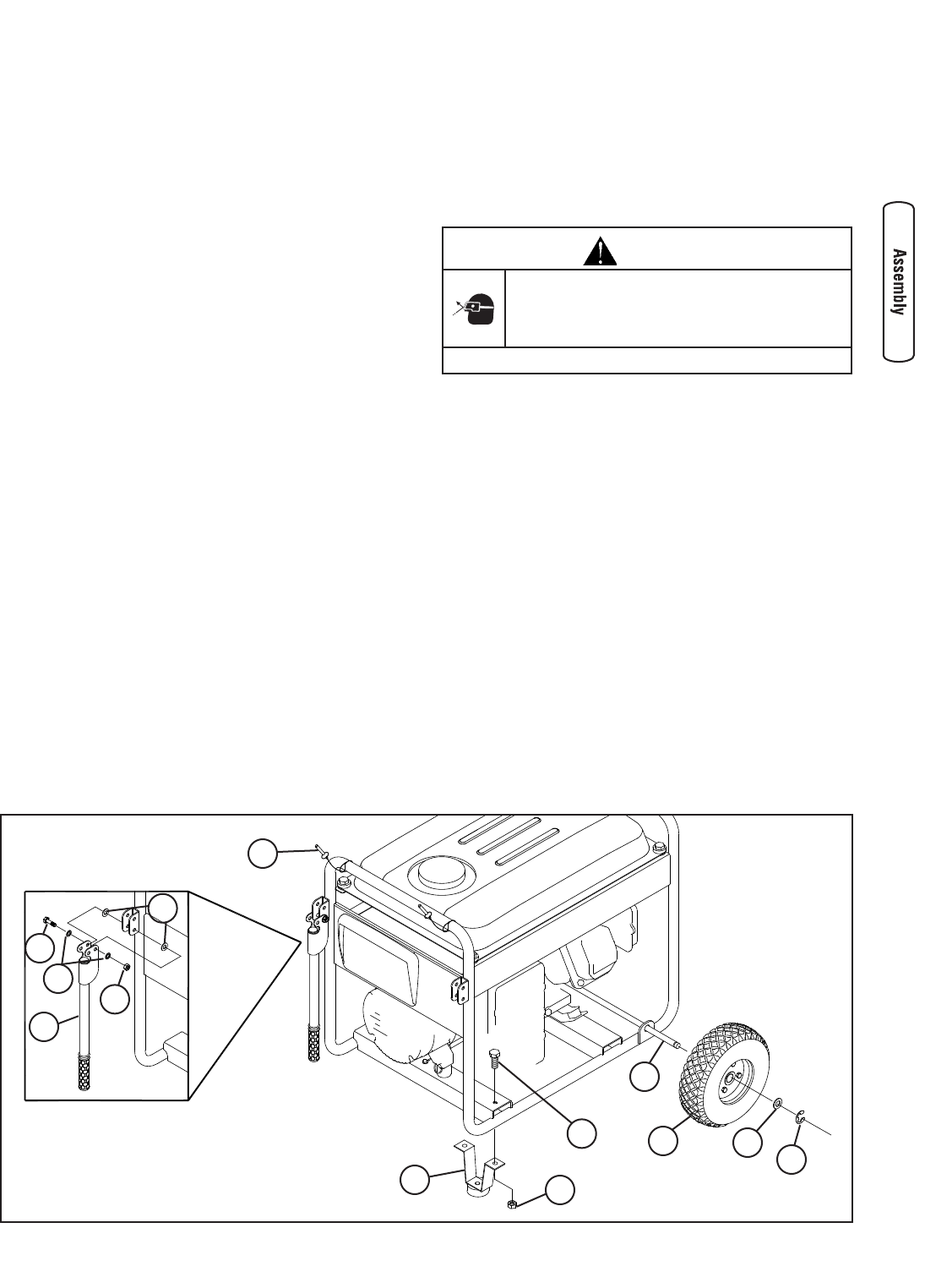
Install the wheel kit as follows:
1. Tip generator so that engine end is up.
2. Slide axle (A) through both mounting brackets.
3. Slide a wheel (B) over axle.
NOTE: Be sure to install wheel with raised hub inboard.
4. Place a washer (C) on axle and then place an e-ring (D)
in axle groove.
CAUTION
E-rings can cause eye injury.
E-rings can spring back and become airborne
when installing or removing.
• Always wear eye protection when installing/removing e-rings.
5. Install e-ring with pliers, squeezing from top of e-ring
to bottom of axle.
6. Repeat steps 3 through 5 to secure second wheel.
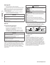
7. Tip generator so that engine side is down.
8. Line up holes in support leg (E) with holes in generator
frame.
9. Attach support leg using 2 capscrews (M8 x 20 mm)
(F) and 2 hex nuts (G). Tighten with a 13 mm socket
wrench and 13 mm wrench.
10. Repeat steps 8 and 9 to secure second support leg.
11. Attach handles (H) to brackets on generator frame as
shown, with 45 mm capscrews (J), flat washers (K),
nylon washers (L), and M8 lock nuts (M).
NOTE: DO NOT overtighten. Handles must be able to move
up and down freely.
12. Return generator to normal operating position (resting
on wheels and support leg).
13. Loop handle pins (N) on generator frame just above
handle brackets.
14. Raise handles and insert handle pins to move generator.
N
J
M
L
K
H
G
F
E
D
C
B
A