


www.HunterFan.com
1.888.830.1326
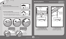
Wiring
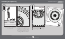
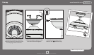
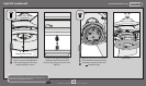
Turn the splices upward and push them carefully back through the hanger bracket
into the outlet box. Spread the wires apart, with the grounded wires on one side of
the outlet box and the ungrounded wires on the other side of the outlet box.
Refer to CAUTION c.1 on pg. 2
10
M3535-01 • 06/18/13 • © Hunter Fan Company
F
R
O
M
R
E
C
E
I
V
E
R
F
R
O
M
C
E
I
L
I
N
G
F
R
O
M
C
E
I
L
I
N
G
B
R
A
C
K
E
T
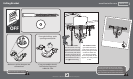
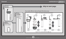
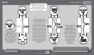
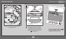
Using an orange wire
connector from
the hardware bag,
connect the 3 grounding
wires (green, green/
yellow stripe, or bare
copper) coming from the
ceiling, downrod, and
hanging bracket.
green/yellow stripe
(grounding)
green/yellow stripe
green/yellow stripe
white
black
blue
white (common out)
black (fan out)
blue (light out)
Note: To connect the wires,
hold the bare metal leads
together and place a wire
connector over them, then twist
clockwise until tight.
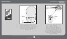
Using the blue wire
connectors from the remote
control hardware bag,
connect the white wire
from the receiver (marked
“common out”) to the white
wire from fan. Connect the
black wire from the receiver
(marked “fan out”) to the
black wire from the fan.
Connect the blue wire from
the receiver (marked ”light
out”) to the blue wire from
the fan. The red wire from
the receiver will not be used,
it has a pre-installed wire
terminator.
F
R
O
M
F
A
N
F
R
O
M
F
A
N
F
R
O
M
R
E
C
E
I
V
E
R
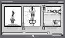
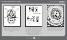
Using an orange wire
connector from
the hardware bag,
connect the black wire
(ungrounded) from the
ceiling to the black wire
from the receiver (marked
“live in”). Connect the
white wire (grounded)
from the ceiling to
the white wire from
the receiver (marked
“neutral in” or
“common in”).
F
R
O
M
C
E
I
L
I
N
G
black (ungrounded)
white (grounded) white (neutral in)
black (live in)