


MA012-01 • 10/01/13
1.888.830.1326
8
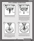
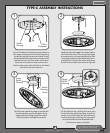
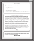
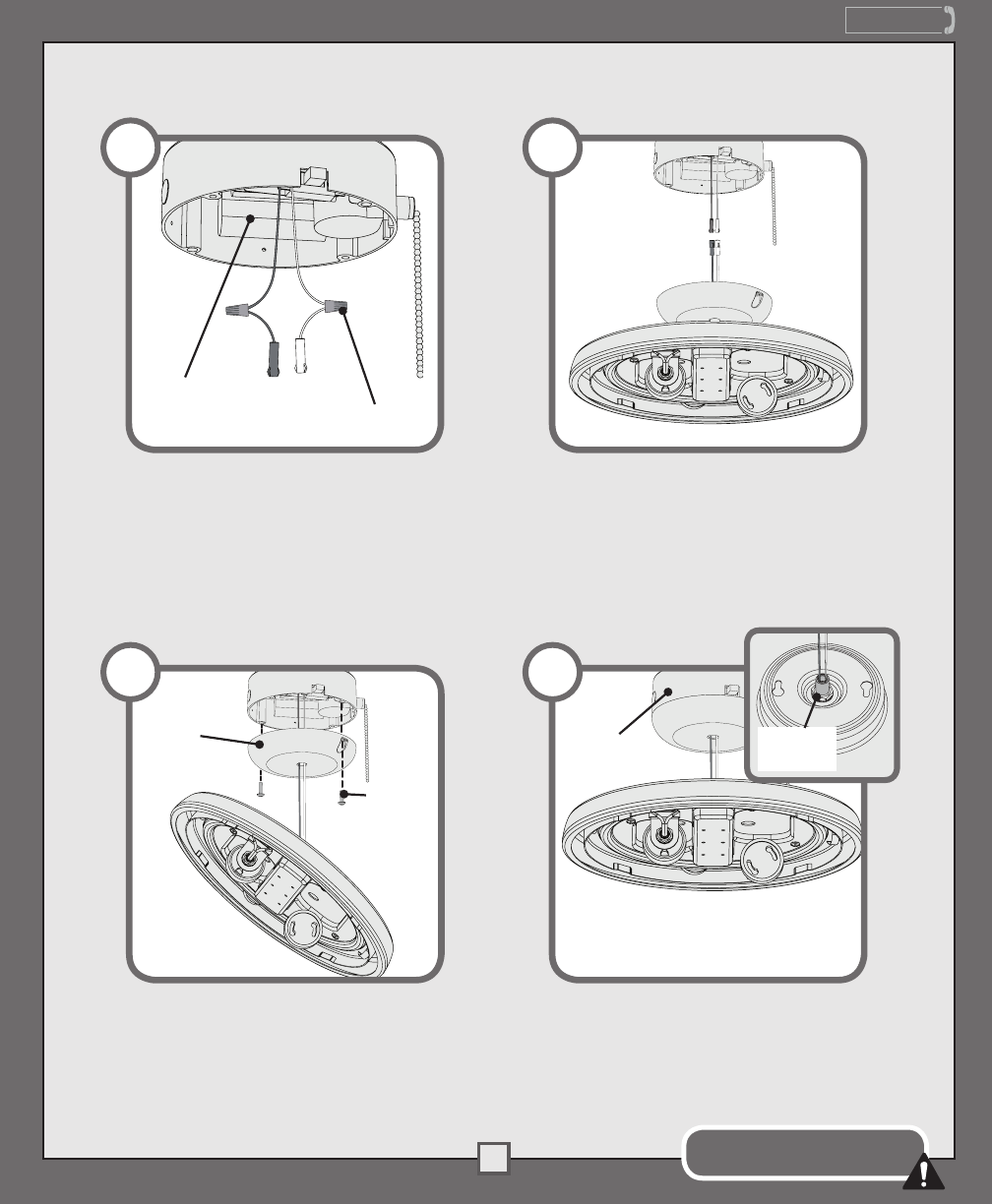
TYPE-C ASSEMBLY INSTRUCTIONS
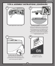
Feed the wires through the center hole in
the switch housing. Then using the single
pin connectors, connect the black or blue
wire from the fan to the black wire from
the light kit. Connect the white wire from
the fan to the white wire from the light kit.
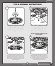
Lift the lower switch housing up so that the
screw holes line up with the holes in the
upper switch housing. Install the switch
housing screws and tighten securely.
Lift the light kit up, tucking the wires into
the hole in the switch housing. Install the
center stem of the light kit into the lower
switch housing by turning the threaded
rod clockwise into the threaded hole.
Continue turning until tight.
Upper
Switch
Housing
4
Threaded
Rod
Lower
Switch
Housing
Switch
Housing
Screw
Wire
Connector
Switch
Housing
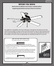
If your fan does not have pin connectors on
the wires coming from the switch housing,
install the wiring harness provided. Using
the provided wire connectors connect the
white wire from the fan to the white wire
from the wire harness and connect the
black or blue wire from the fan to the black
wire from the wire harness.
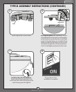
Do not allow the light kit to hang
only by the wire connections!
1 2
3