


41490-01 03/12/2009
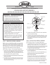
3. Insert the chain and fan pull chain switch thr ough
the round opening on the side of the modular
accessory light kit. Thr ead the bellmouth nut over
the pull chain and hand-tighten the bellmouth
nut.
4. Reattach the patented breakaway connector to
the end of the pull chain.
5. Insert the reversing switch into the square hole
on the side of the modular accessory light kit.
Install and tighten the two scr ews you r emoved
in Step 1, substep 1.
6. Carefully place the capacitors in the modular ac-
cessory light kit.
You have completed the assembly of the modular
accessory light kit and are ready for installing the
modular accessory light kit to the fan.
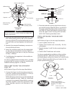
STEP 3: INST ALLING THE ACCESSOR Y
LIGHT KIT
NOTE: Refer to Figure 3 for the steps listed below.
1. Connect the lower (mutli-wire) plug connector
from the modular accessory light kit to the up-
per plug connector fr om the motor.
NOTE: Both plug connectors ar e polarized and will
only t together one way . Make sur e that both
connectors are properly aligned before connect-
ing them together. Incorrect connection could
cause improper operation and damage to the
product.
2. Place the modular accessory light kit over the up-
per switch housing. Align the side scr ew holes in
the upper switch housing and the modular acces-
sory light kit. Attach the modular accessory light
kit to the upper switch housing with the three
#6-32 X 3/8" housing assembly screws.
STEP 4: INSTALLING THE BULBS AND
GLOBES
NOTE: Refer to Figur e 4 for the steps listed below.
1. Insert a globe into the cup.
2. Tighten the thumbscrews manually. Do Not
overtighten.
3. Repeat substeps 1 and 2 for the remaining three
globes.
4. Install a 13W CFL bulb into
each socket.
You have completed the installation of the modular
accessory light kit. Refer back to the “Operating
and cleaning your ceiling Your Hunter Fan” section in the
Owner’s Manual provided with your Hunter fan for
proper operation instructions.
CUP
THUMB-
SCREWS
GLOBE
FIGURE 4
Hunter Fan Company
7130 Goodlett Farms Pkwy.
Memphis, TN 38016
USA
© 2009 Hunter Fan Co.
FIGURE 2
Fan Speed
Switch
Capacitor
Reverse Switch
Multi-wire Plug
Connection
Capacitor
Bellmouth Nut
#6-62 Housing
Assembly Screws
Bellmouth Nut
Light Switch
Wires to Light Sockets
CAUTION
Be sure no bare wire or wire strands are visible after
making connections.
UPPER SWITCH
HOUSING
UPPER PLUG
CONNECTOR
HOUSING ASSEMBL Y
SCREW
FIGURE 3
LOWER PLUG
CONNECTOR
LIGHT KIT