


L4031A,C POOL HEATER AQUASTAT
®
CONTROLLER
60-2107—5
4
M8815
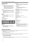
CLAMP B
CLAMP A
CLAMP SCREWS (2)
BULB
COMPRESSION
FITTING
SEALING
WASHER
BULB
INSERTION LENGTH
APPROX. 3-3/16 in. (81 mm)
SPLIT SLEEVE
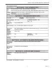
Fig. 2. 104486 Bulb compression fitting.
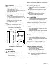
Using Capillary Compression Fitting (Fig. 3)
1. Screw fitting into boiler or pipe tapping.
2. Place packing nut on tubing.
3. Slide bulb completely through fitting.
4. Place composition disk and four slotted brass washers
on tubing in the order shown in Fig. 3. Turn brass
washers so that slots are 180 degrees apart.
5. Slide seal assembly into fitting and tighten packing nut.
COMPOSITION DISK
(SLOTTED)
BOILER PLUG
CAPILLARY TUBING
EXAMPLE OF SLOTTED WASHERS
ASSEMBLED
IN PAIRS:
PACKING NUT
M8816
IMMERSION
BULB
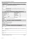
Fig. 3. 104484 Capillary compression fitting.
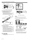
Using Immersion Well (Fig. 4)
1. Screw the well into the boiler or pipe tapping.
2. Insert the bulb into the well, pushing the tubing until the
bulb bottoms in the well.
3. Attach the retainer clamp to the end of the well spud.
Loosen the draw nut and spread the jaws of the clamp
with a screwdriver if necessary. See Fig. 4.
4. With the retainer clamp attached to a well spud (be
sure jaws of clamp hook over the ridge at the end of the
spud, as shown at point A), adjust tubing to fit through
retainer clamp groove, as shown at point B.
5. Tighten draw nut so retainer clamp is firmly attached to
well spud and tubing is held securely in place.
CAUTION
Do not secure draw nut so tightly that retainer clamp
could collapse tubing
M8777
WELL
BULB
SPUD
MOUNTING
CLAMP
A
DRAW
NUT
TUBING
B
INSERT— MOUNTING CLAMP
SCREWDRIVER
SPREAD JAWS
TO FIT OVER
RIDGE ON SPUD
OF WELL
JAWS
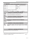
Fig. 4. Immersion well fitting.
Wiring
All wiring must comply with local codes and ordinances.
In all installations, follow the equipment manufacturer
instructions. If not available, use hookups in Figs. 5, and 6.
REVERSE-ACTING
PRESSURE
CONTOLLER
HEATING
SWITCH
PUMP
PUMP
SWITCH
L4031 POOL HEATER
AQUASTAT® CONTROLLER
POOL
CONTROL
HIGH
LIMIT
M4539
PILOTSTAT
GAS VALVE
L1
(HOT)
L2
1
1
2
2
POWER SUPPLY. PROVIDE DISCONNECT MEANS AND
OVERLOAD PROTECTION AS REQUIRED.
WHEN HIGH LIMIT AND POOL CONTROL ARE CONNECTED IN
SERIES, CURRENT DRAW OF CIRCUIT MUST NOT EXCEED
ELECTRICAL RATING OF POOL CONTROL.
Fig. 5. Typical L4031 connection providing pool
temperature control and high limit protection.