


Page 8 — English
UNPACKING
This product requires assembly.
Carefully remove the product and any accessories from
the box. Make sure that all items listed in the packing list
are included.
WARNING:
Do not use this product if any parts on the Packing List
are already assembled to your product when you unpack
it. Parts on this list are not assembled to the product by
the manufacturer and require customer installation. Use
of a product that may have been improperly assembled
could result in serious personal injury.
NOTE: This tool is heavy. To avoid back injury, lift with
your legs, not your back, and get help when needed.
Inspect the tool carefully to make sure no breakage or
damage occurred during shipping.
Do not discard the packing material until you have care-
fully inspected and satisfactorily operated the tool.
If any parts are damaged or missing, please call
1-800-242-4672 for assistance.
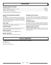
PACKING LIST
Pressure Washer
25 ft. High Pressure Hose
Trigger Handle
Spray Wand
Quick-Connect Nozzles (3) with Nozzle Storage
Nozzle Cleaning Tool
Injection Hose
Wheel (2)
Axle (2)
Hitch Pin (2)
4-Cycle Engine Lubricant (SAE 30)
Telescoping Handle
Operator’s Manual
WARNING:
If any parts are damaged or missing do not operate this
product until the parts are replaced. Use of this product
with damaged or missing parts could result in serious
personal injury.
WARNING:
Do not attempt to modify this product or create acces-
sories not recommended for use with this product. Any
such alteration or modification is misuse and could result
in a hazardous condition leading to possible serious
personal injury.
WARNING:
To prevent accidental starting that could cause serious
personal injury, always disconnect the engine spark plug
wire from the spark plug when assembling parts.
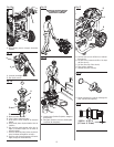
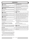
ATTACHING THE WHEEL ASSEMBLY
See Figure 2.
To attach the wheels to the pressure washer base:
Locate the axle, hitch pins, and wheels. Remove the hitch
pin from the axle.
Slide the axle through the hole in the center of the wheel.
Lift the machine and slide the combination into the wheel
mounting hole in the machine base as shown.
Push the hitch pin into the hole on the end of the axle to
secure the wheel assembly.
NOTE: The hitch pin should be pushed into the axle until
the center of the pin rests on top of the axle.
Repeat with the second wheel.
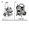
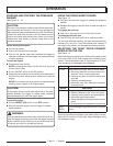
INSTALLING THE TELESCOPING HANDLE
See Figure 3.
To install the telescoping handle:
Align the arrows on the U-shaped handle with the arrows
on the back of the frame.
Push and hold the button on the handle as you slide the
handle into the holes in the frame.
Lock the handle in place by aligning the slot in the handle
lock cap with the pin on the housing bar. Next, push the
handle lock cap down while turning the cap clockwise.
NOTE: Before use, pull the handle up until the lock
button snaps through the locking slot to secure the
handle in place.
ASSEMBLY