


Page 14 — English
ASSEMBLY
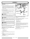
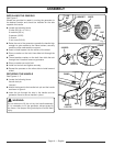
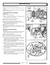
Fig. 3
wheel
spacer
wheel
B
olt
INSTALLING THE WHEELS
See Figure 3.
Wheels are provided to assist in moving the generator to
the desired location and should be installed on the side
opposite the handle.
Locate the following items:
2 bolts (3/8-16 x 4-1/4 in.)
6 washers (3/8 in.)
2 spacers (.38 ID)
2 wheels
2 lock nuts (3/8-16)
Raise the end of the generator opposite the handle
high
enough to gain access to the frame bottom; securely
position props underneath to support.
Insert a wheel spacer into the center of the wheel.
Place a washer on the bolt, then slide bolt through the
wheel.
Thread another washer on the bolt, then slide the bolt
through the U-bracket frame on generator.
Place a washer on end of bolt.
Install nut on bolt and tighten securely.
Repeat the process on the other side to install second
wheel.
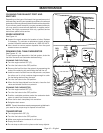
SECURING THE HANDLE
See Figures 4 - 5.
Locate the following items:
Handle lock pin
Lanyard
Attach the lanyard to the handle lock pin and the handle
as shown in figure 4.
Insert the pin through the hole in the handle and the
generator frame to secure handle in place.
WARNING:
Do not attempt to lift the unit by the handle assembly.
If it is necessary to lift the generator, always grasp by
the frame. Use proper lifting techniques to avoid back
injury.
Fig. 4
Fig. 5
lock
nUt
washer
washer
handle
lock pin
lanyard
fraMe
handle
lock pin
handle
hole
fraMe
U-Bracket