UK - Page 28
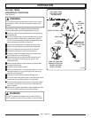
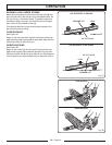
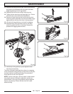
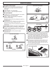
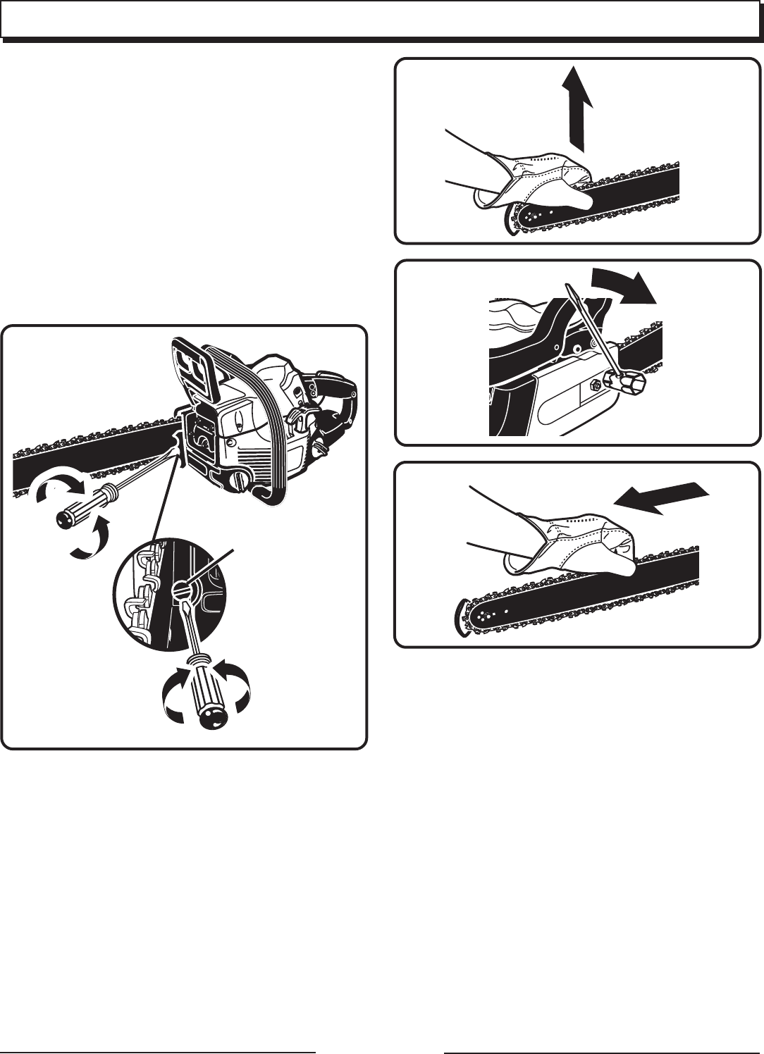
11. Replace the outer guide bar plate, ensuring that the bar
pin groove is at the bottom with the upper and lower
edges angled away from the guide bar.
12. Replace the clutch cover and bar mounting nuts.
13. Tighten the bar mounting nuts finger tight only. The bar
must be free to move for tension adjustment.
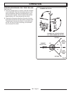
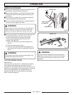
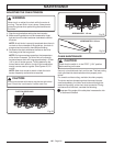
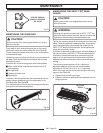
14. Remove all slack from the chain by turning the chain
tensioning screw clockwise until the chain seats snugly
against the bar with the drive links in the bar groove.
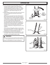
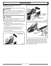
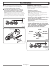
15. Lift the tip of the guide bar up to check for sagging.
16. Release the tip of the guide bar and turn the chain
tensioning screw half a turn clockwise. Repeat this
process until sagging does not exist.
CHAIN
TENSIONING
SCREW
Fig. 48
17. Hold the tip of the guide bar up and tighten the bar
mounting nuts securely.
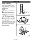
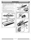
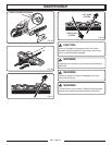
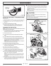
The chain is correctly tensioned when there is no sagging
on the underside of the guide bar and the chain is snug, but
can be turned by hand without binding. Ensure that the
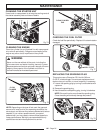
chain brake is not set. See Figure 51.
NOTE: If chain is too tight, it will not rotate. Loosen the bar
nuts slightly and turn the tension adjuster a quarter turn
anticlockwise. Lift the tip of the guide bar up and retighten
the bar nuts securely. Ensure that the chain will rotate
without binding.
Fig. 49
Fig. 50
Fig. 51
MAINTENANCE


