


7
English
NOTE
Helpful information for correct function and use.
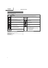
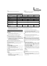
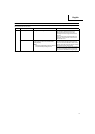
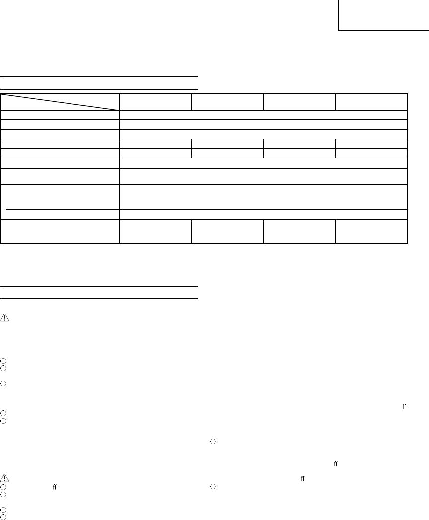
SPECIFICATIONS
MODEL
CH22EAP2 (50ST)
CH22EA2 (50ST)
CH22EBP2 (62ST)
CH22EB2 (62ST)
CH22ECP2 (62ST)
CH22EC2 (62ST)
CH22ECP2 (78ST)
CH22EC2 (78ST)
Engine Size (ml) 21.1
Spark Plug NGK BMR 7A (Europe and Australia) or Champion CJ 6 (other regions)
Fuel Tank Capacity (l) 0.30
Dry Weight (kg) 4.3 4.7 5.0 5.2
Overall blade length (mm) 500 620 620 780
Blade type
Double-sided
Sound pressure level
LpA (dB(A)) (ISO 10517) 97
Sound power level
Lw measured (dB (A))
(2000/14/EC, ISO 10517)
102
LwA (dB (A)) 104
Vibration level (m/s
2
) (ISO 10517)
Front handle
Rear handle
7.0
7.5
9.1
9.1
2.8
3.4
2.8
2.8
NOTE
Equivalent noise level/vibration level are calculated as the time-weighted energy total for noise/vibration levels under various working
conditions with the following time distribution : ISO 10517.....1/5 idle, 4/5 racing. 2000/14/EC.....only racing.
* All data subject to change without notice.
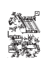
OPERATING PROCEDURES
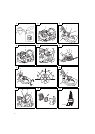
Fuel (Fig. 1)
WARNING
The hedge trimmer is equipped with a two- stroke engine.
Always run the engine on fuel, mixed with oil.
Provide good ventilation, when fueling or handling fuel.
Fuel
Always use branded 89 octane unleaded gasoline.
Use genuine two-cycle oil or use a mix between 25:1 to 50:1,
please consult the oil bottle for the ratio or Hitachi dealer.
If genuine oil is not available, use an anti-oxidant added quality
oil expressly labeled for air-cooled 2-cycle engine use (JASO
FC GRADE OIL or ISO EGC GRADE). Do not use BIA or TCW
(2-stroke water-cooling type) mixed oil.
Never use multi-grade oil (10W/30) or waste oil.
Always mix fuel and oil in a separate clean container.
Always start by fi lling half the amount of fuel, which is to be used.
Then add the whole amount of oil. Mix (shake) the fuel mixture. Add
the remaining amount of fuel.
Mix (shake) the fuel-mix thoroughly before fi lling the fuel tank.
Fueling
WARNING (Fig. 2)
Always shut o the engine before refueling.
Slowly open the fuel tank (1), when fi lling up with fuel, so that
possible over-pressure disappears.
Tighten the fuel cap carefully, after fueling.
Always move the unit at least 3 m from the fueling area before
starting.
Before fueling, clean the tank cap area carefully, to ensure that
no dirt falls into the tank. Make sure that the fuel is well mixed by
shaking the container, before fueling.
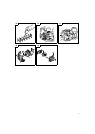
Starting
CAUTION
Before starting, make sure the cutting attachment does not
touch anything.
1. Set stop switch (2) to ON position (A). (Fig. 3)
* Push priming pump (4) several times so that fuel fl ows through
the pump or return pipe. (Fig. 4)
CAUTION
Do not disassemble the recoil starter. you may get a possibility
of personal injury with recoil spring.
2. Set choke lever (5) to CLOSED position (B). (Fig. 5)
3. Pull recoil starter briskly, taking care to keep the handle in your
grasp and not allowing it to snap back. (Fig. 6)
4. When you hear the engine attempts to start, return choke lever
to RUN position (open) (C). Then pull recoil starter briskly
again.
NOTE
If engine does not start, repeat procedures from 2 to 4.
5. After starting engine, allow the engine about 2-3 minutes to
warm up before subjecting it to any load.
Cutting
When cutting, operate engine at full throttle as this maintains proper
blade speed. When trimming top of hedge, hold trimmer so blades
are between 15 and 30 degrees from a horizontal position and
swing trimmer in an arc toward edge of hedge to sweep cuttings o .
When trimming sides of hedge, hold blade vertically and swing unit
in an arc.
NOTE
Multi-position twist handle (Fig. 7)
The rear control handle turns 90 degrees to provide
comfortable use while accommodating a variety of cutting
angles. The handle allows for fi ve di erent locking positions.
Before attempting to adjust rear handle, make sure the machine
is at idle or engine is shut o .
The throttle lever cannot be engaged if the handle is not
secured (the lock lever is pressed).
To rotate the handle; push the lock lever (6) allowing the handle
to turn. Rotate the handle to the desired 0°, 45° or 90° locking
position and release the lock lever (6) to lock the handle in
place.
D: LOCK
E: UNLOCK
Stopping (Fig. 8)
Decrease engine speed, and push stop switch to stop position (F).
NOTE
If the engine does not stop, it can be forced to stop by rotating
the choke lever to the choked position.
Before restarting the engine, ask Hitachi Authorized Service
Centers for repairs.