


Model 8663A
Service
SERVICE SHEET 14
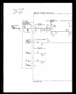
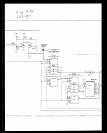
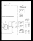
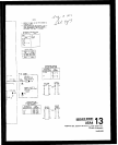
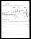
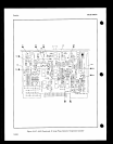
A5A3 FRACTIONAL-N LOOP PHASE DETECTOR
REFERENCE BLOCK DIAGRAM 4
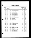
Table 4-l. Recommended
I’erfoymance
Tests
After Adjustments or Repairs
Table 5-2. Post-Repair Adjustment Procedures
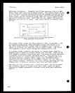
PRINCIPLES OF OPERATION
General
The
purpose of the Fractional-N Loop Phase Detector (A5A3) is to
dwelwp
the
FN
Loop Error Voltage which is used to tune the VCO.
This FN Loop Error Voltage (tuning voltage) is developed by
integrating currents from the Phase Detector circuit, the
Fractional-N Correction Pulse ?Jidth to Current Converters, and the
Bias
Sink
circuit.
These currents are integrated together by the
Current Summing Amplifier to develop a voltage. The Sample and Hold
circuit
samples the voltage output from the Current Summing Amplifier
once each reference period and at the same time during each reference
period. The sampled voltage becomes the FN Loop Error Voltage.
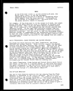
When the Fractional-N Loop (FN Loop) is phase-locked, the tune
voltage must be a constant dc value,
This means the voltage output
from the Current Summing Amplifier must be the same at every sample
period. In order to meet this condition the total of the currents
being integrated must be the same each reference period.
To look at
it another way, the currents entering the summing node must equal the
currents
leaving the summing node in order for the tune voltage to
remain constant. This concept,
that when the FN Loop is
phase-locked, the currents entering the summing node equal. the
currents
leaving the node is true for aI1 conditiwns, that is, for
the
condition when the loop runs without a fractional part and for
the
condition when it has a fractional part.
The difference is that
when the loop operates with no fractional part the output from the
Phase Detector ci,rcuit remains constant. However,
when the loop
operates with a fractional part, the output from the Phase
Detector
circuit no longer remains constant but varies from reference period
to reference period. To compensate for the changing phase detector
output the outputs from the Fractional-N Correction Pulse Width to
Current
Converters must also change. For example, if the Phase
Detector circuit supplies less current to the summing node, the
Fractional-N Correction Pulse Width to Current Converters must supply
more current so that the current entering the summing node is always
a constant value.
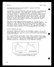
Phase Detector
The Phase Detector consists of a pair of flip-flops, U5A and B, and
gates U4D and U~C.
The purpose of the Phase Detector is to generate
a pulse width proportional to the phase difference betw@en its two
input signals, the FN Loop IF (VCO/N) and the FN Loop PM Det
8.407