


3Hearth & Home Technologies • GFK-210 Blower System Instructions 2206-938 Rev. H • 7/11
5.0 INSTALLING THE VARIABLE SPEED
CONTROL AND TEMPERATURE SENSOR SWITCH
If using a remote control system that utilizes a blower
(fan) control, disregard steps 1-3 and follow remote con-
trol installation instructions.
NOTICE! The sensor switch and rheostat are not used
if the blower is controlled with the RC300 remote control.
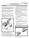
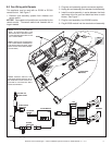
1. Remove the knob and locknut from the variable speed
control. Slide the variable speed control behind the
control panel. With the stem sticking out of the pre-
punched hole, attach the locknut tightly and reattach
the knob on the stem. See Figure 4. Turn the speed
control switch to the "ON" position.
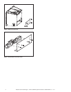
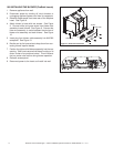
2. Slide the temperature sensor switch onto the blower
stud located on the bottom of the combustion box. See
Figure 3. Secure the temperature sensor switch with
the wing nut provided.
NOTICE: The blower stud is located on the bottom of the
combustion box. See Figure 5.
NOTICE: The temperature sensor switch must be installed
so that the sensor switch is facing the combustion box
surface. See Detail A of Figure 5.
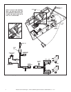
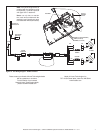
3. Connect the variable speed control and the temperature
sensor switch to the power cord. See Figure 6.
4. Gather the loose wires underneath the appliance and
use the zip ties to restrain them and keep them away
from the blower wheel (fan blades). See Figure 6,
Detail A.
5. Turn the 110-120 VAC service "ON" at the circuit
breaker.
6.0 RECOMMENDED OPERATING PROCE-
DURES WHEN VARIABLE SPEED CONTROL AND
TEMPERATURE SENSOR SWITCH ARE USED
Ignite the fi re in the fi replace with the variable speed control
switch in an "ON" position. The fan will automatically turn
on when the temperature sensor switch closes at approxi-
mately 110
O
F. Heated air will be delivered at the outlet
grille. The fan will continue to operate after the fi replace
is turned OFF until the temperature sensor switch opens.
NOTICE! During operation, ensure that all wiring is
kept away from the blower wheel (fan blades).
Various conditions (such as fi replace model, type of fi re-
place installation, outside air temperature vs. inside air
temperature) can contribute to the length of the time the
blower remains on after the fi replace is turned OFF. The
blower can be turned off manually with the speed control
switch.
WARNING! Risk of Injury! DO NOT contact the blower
wheel (fan blades) during operation.
7.0 MAINTENANCE
Periodically check the fi replace and remove any dust, dirt
or obstructions.
8.0 REPLACEMENT PARTS AND CUSTOMER
SERVICE
Replacement parts and service may be obtained through
your dealer.
Hardware Bag: SRV107-570A
Figure 5
TEMPERATURE SENSOR SWITCH
COMBUSTION BOX SURFACE
BLOWER STUD
BLOWER
STUD
VARIABLE
SPEED
CONTROL
TEMPERATURE
SENSOR
SWITCH
DETAIL A